Anesthesia breathing circuit tube support

a technology of breathing circuit and tube support, which is applied in the field of medical devices, can solve the problems of more injury than surface damage, damage may occur, and achieve the effect of shortening the length and increasing the length

Inactive Publication Date: 2015-09-08
BLAYLOCK REBECCA C
View PDF13 Cites 9 Cited by
  • Summary
  • Abstract
  • Description
  • Claims
  • Application Information

AI Technical Summary

Benefits of technology

[0030]The present invention overcomes the aforementioned problems, and is distinguished over the prior art in general, and these patents in particular by a breathing tube support device that attaches to a patient or optionally to a support surface for holding, supporting, and selectively positioning conventional flexible tubes or hoses of a breathing circuit during provision of anesthesia, assisted and artificial ventilation, and/or spontaneous ventilation. The breathing tube support device has a flexible support arm formed of a length of flexible axially extendable and collapsible corrugated tubing, a mounting base at a bottom end thereof for attachment to the patient or support surface, and a breathing tube holder member at a top end thereof for re

Problems solved by technology

The endotracheal tube placed in a patient's larynx and connected to the breathing circuit can cause more injury than is generally appreciated.
Even brief incubation for surgical procedures may cause surface damage.
Damage may occur wherever the endotracheal tube comes in contact with tissue although the larynx and trachea are particularly at risk.
A minor area of insult may be followed by spontaneous resolution, or a devastating sequence of events leading to irreversible injury.
Movement of the endotracheal tube caused by manipulation of the surgeon during anesthesia, such as in a sitting shoulder operation, can cause shearing forces that add to the abrasion of the mucosa.
Research studies have shown that excessive movement of the tube during assiste

Method used


Image

  • Anesthesia breathing circuit tube support
  • Anesthesia breathing circuit tube support
  • Anesthesia breathing circuit tube support

Examples


Embodiment Construction

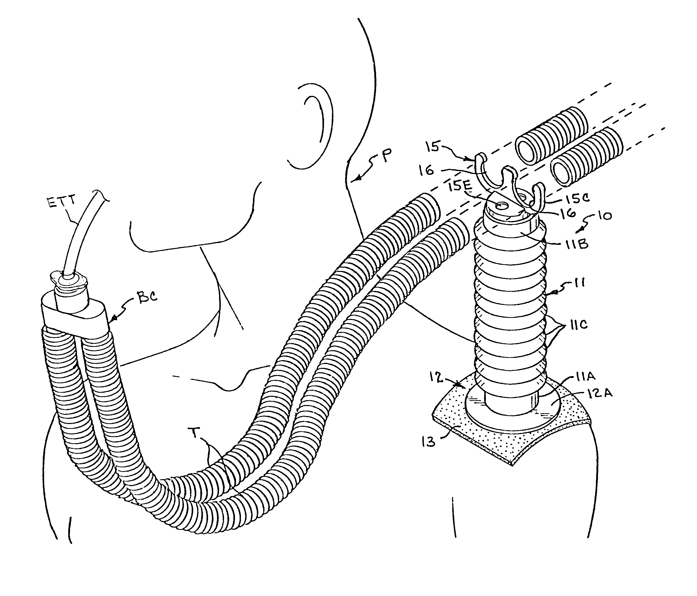
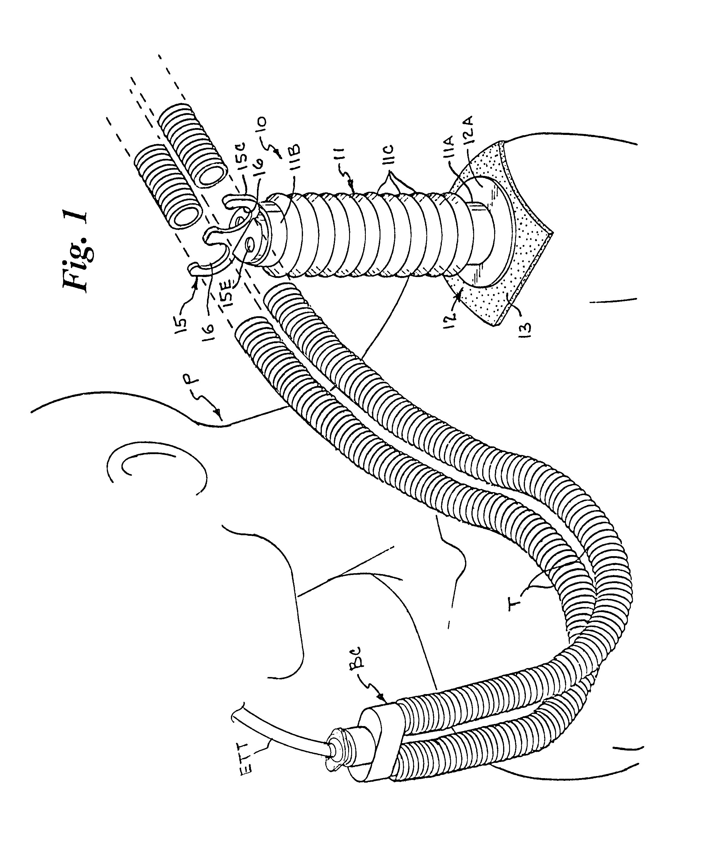
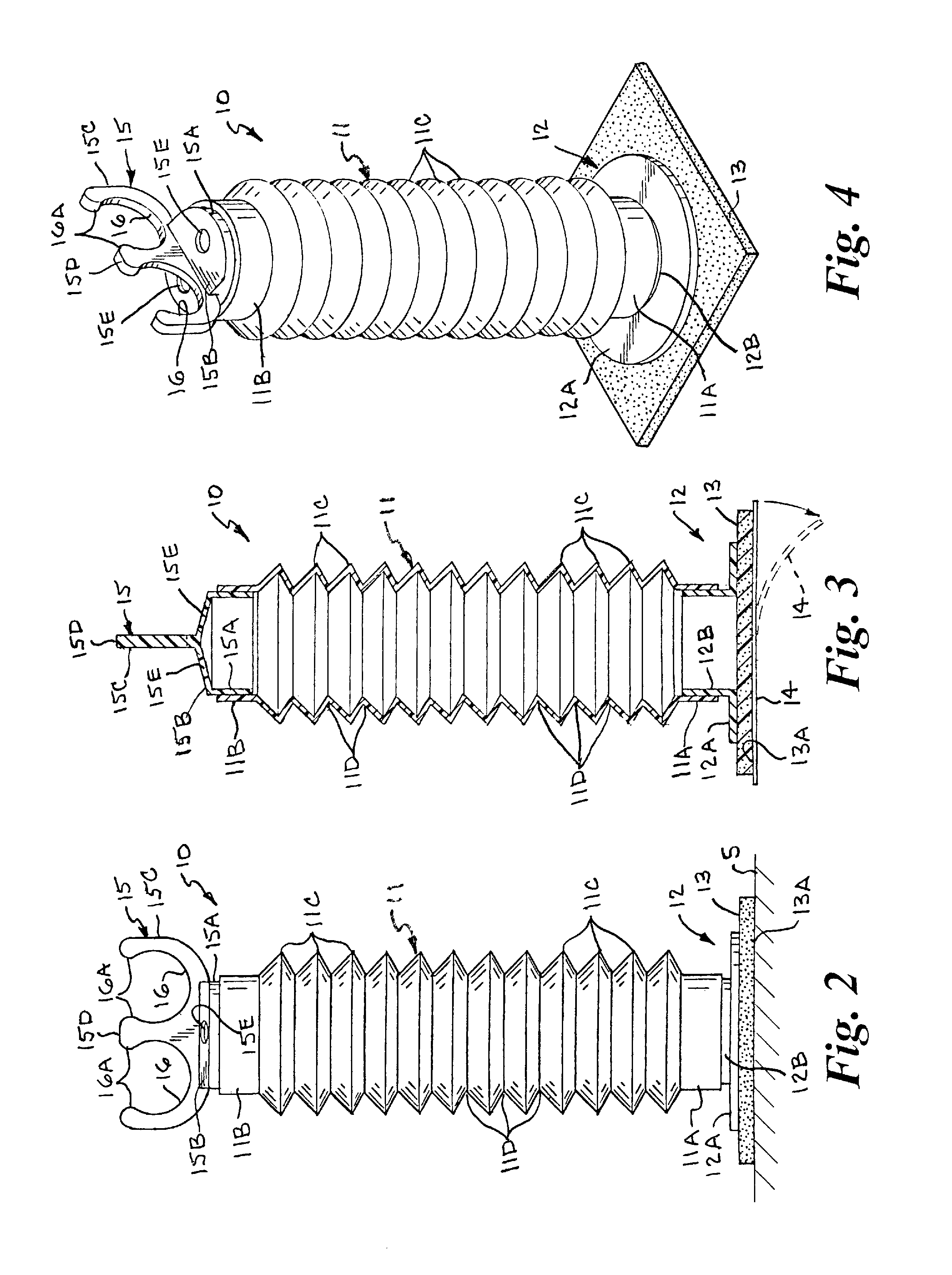
[0044]Referring now to the drawings by numerals of reference, and particularly to FIG. 1, the present breathing tube support device 10 attaches to a patient or other support surface for holding, supporting, and selectively positioning conventional flexible tubes or hoses T of a breathing circuit BC during provision of anesthesia, assisted and artificial ventilation, and / or spontaneous ventilation. For purposes of example only, and not limited thereto, the breathing tube support device 10 is shown in FIG. 1 attached to a patient P and the exemplary breathing circuit BC shown is a “dual-limb” circuit which includes an expiratory tube and an inspiratory tube formed of flexible corrugated tubing that are coupled at the patient end to a conventional endotracheal tube ETT, a portion of which is shown. The other end of the flexible tubes or hoses T of the breathing circuit BC are connected in a conventional manner to an anesthesia machine (conventional and therefore not shown). FIG. 2 show...


PUM


Abstract

A breathing tube support device for holding and supporting one or more flexible breathing tube(s) of a breathing circuit during provision of anesthesia, assisted and artificial ventilation and/or spontaneous ventilation has a flexible support arm formed of a length of flexible axially extendable and collapsible corrugated tubing, a mounting base at a bottom end thereof for attachment to the patient or a support surface, and a breathing tube holder a top end thereof for receiving and supporting a section of the breathing tube(s). The flexible support arm can be expanded to increase its length longitudinally and collapsed upon itself to shorten its length longitudinally, and is sufficiently flexible to assume a bent or curved configuration, and sufficiently stable to retain the bent or curved configuration, whereby breathing tube(s) held and supported by the device can be optimally positioned relative to the patient's head and neck area.

Description

BACKGROUND OF THE INVENTION[0001]1. Field of the Invention[0002]This invention relates generally to the field of medical devices and, more particularly to a breathing tube support device having a flexible support arm that is axially extendable and collapsible and capable of assuming a bent or curved configuration with a mounting base at a bottom end for attachment to a patient or support surface and a breathing tube holder member at a top end thereof for holding, supporting, and selectively positioning conventional flexible tubes or hoses of a breathing circuit during provision of anesthesia, assisted and artificial ventilation, and / or spontaneous ventilation.[0003]2. Background Art[0004]21 CFR §868.5240 (a) defines an “anesthesia breathing circuit” as a device that is intended to administer medical gases to a patient during anesthesia. It provides both an inhalation and exhalation route and may include a connector, adaptor, and Y-piece. 21 CFR §868.5280 (a) defines a “breathing tub...

Claims


Application Information

Patent Timeline
IPC IPC(8): F16M13/00A61M16/08A62B18/08
CPCA61M16/08A62B18/08A61M16/0875A61M2209/082A61M2209/088A61M16/0833
Inventor BLAYLOCK, REBECCA C.
Owner BLAYLOCK REBECCA C
Why Eureka
Try Eureka