Concealed-fastener exterior cladding panels for building construction

a technology of exterior cladding and concealed fasteners, which is applied in the direction of roofs, coverings/linings, building components, etc., can solve the problems of difficult stacking of metal panels during transportation or storage, affecting the decorative appearance of metal panels, and high production costs, and achieves excellent shear strength and stiffness

Active Publication Date: 2015-09-08
LESTER BUILDING SYST
View PDF15 Cites 28 Cited by
  • Summary
  • Abstract
  • Description
  • Claims
  • Application Information

AI Technical Summary

Benefits of technology

[0017]An exterior cladding panel assembly for covering an outside surface of a framed building is provided by the invention. A unique rib and batten system allows through fastening of wide panels on the order of 32 inches or greater to the building's underlying framing structure with complete concealment of the fasteners. The panels are substantially planar with a female raised major rib along their first lateral edge, a supporting male end rib along the opposite lateral edge, and full raised major ribs along interior positions therebetween. These female and male edge ribs are formed along the panels such that when the female rib of one panel laps over the male rib of the other panel to form an interconnected panel assembly, proper panel alignment is produced. The lapped ribs of the panels are then attached to the underlying framing of the building structure by means of a common nail or screw driven through the raised ribs with a space between the rib top surface and the underlying framing member, thereby resulting in a shear connection with the associated bracing properties, thereby enhancing the building's structural integrity.
[0018]The ribs are formed with an inverted U-shaped end profile, instead of a W-shaped end profile found in the prior art, to eliminate two vertical legs and reduce materials and manufacturing costs for the panels and make it easier for a construction worker to attach them to the building. The ribs are formed with longitudinal detents in each face. A batten cap is snapped into engagement with these longitudinal detents along the major rib to cover the nail or screw heads to render the panels moisture and weather-resistant.
[0019]The overlapping female and male ribs of the through-fastened, fastener-concealed panels of the present invention produce “stitched edges” in combination with the common fastener driven through the lapped ribs to prevent movement between the panels. These stitched panels transfer shear forces via tension fields from one panel to the next panel. It is this force transfer that enables the stitched panels to function as the shear transfer element of the diaphragm system, thus eliminating the need for sub-sheathing to perform that function. The through-fastened, fastener-concealed panels of the present invention also eliminate the need for clips used in the prior art systems to attach the panels to the underlying framing members. This saves material and labor costs, while enabling more direct, stronger, and rigid connection between the panel and the structural framing. Also, the panels of the present invention are designed, so that they can be installed to the roof without the need for solid backing material. This feature saves the materials and labor needed to install the filler. The flat region of the panels between the major ribs preferably includes at least one inverted minor rib having a substantially flat bottom surface. The bottoms of the minor ribs are slightly lower than the exposed flat panels. Thus, the panel flats do not make firm contact with the purlins. This minor rib acts to break up the flat region to stiffen its material to decrease the natural tendency of the panel to move towards and away from the building's underlying framing members to produce undulations in the panel's flat regions (“oil canning”). These minor ribs also space the panel a slight distance from the framing member to reduce the natural tendency of the panel to telegraph (“show”) the form of the underlying framing member in its material (“ghosting”).
[0020]The ribs taper from wide at the bottom to narrow at the top. This taper allows the panels to nest. Nesting panels simplifies shipping, thereby reducing transport costs. Moreover, the panels may be stacked on top of each other during storage or at a construction site.
[0021]In a preferred embodiment, special nails or screws having an extended shank with a substantial solid portion of the shank without threads are used to secure the panel assembly to the framing member. By driving the extended shank portion of the screw or nail below the framing member surface, wind-induced uplift of the panel assembly is reduced while also reducing wind-induced shearing of the screws or nails along the outer surface of the framing member.
[0024]The through-fastened, fastener-concealed panels of the present invention are designed to span open purlins, No structural sheathing is required. Assemblies that include the panels have excellent shear strength and stiffness. These assemblies therefore can be used as part of the building's lateral load-resisting system.

Problems solved by technology

However, the fastener heads directly show on top of the metal panels, which can interfere with the decorative appearance of the metal panels, especially if the fastener heads were not fastened with uniform spacing along the metal panels.
Such elaborate shapes can be expensive to produce and make it difficult to stack the metal panels during transport or storage.
Moreover, many of them require these clips to be precisely positioned along the rafters before the metal panels are laid down on the rafters, which slows down the roof assembly process.
Still another disadvantage of standing-seam panels is the fact that they cannot brace the framing structure of the building in the way that through-fastened panels do.
Furthermore, standing-seam panels cannot form a structural diaphragm, and therefore are not part of the building's lateral load system.
This can be a time-consuming process.

Method used


Image

  • Concealed-fastener exterior cladding panels for building construction
  • Concealed-fastener exterior cladding panels for building construction
  • Concealed-fastener exterior cladding panels for building construction

Examples


Embodiment Construction

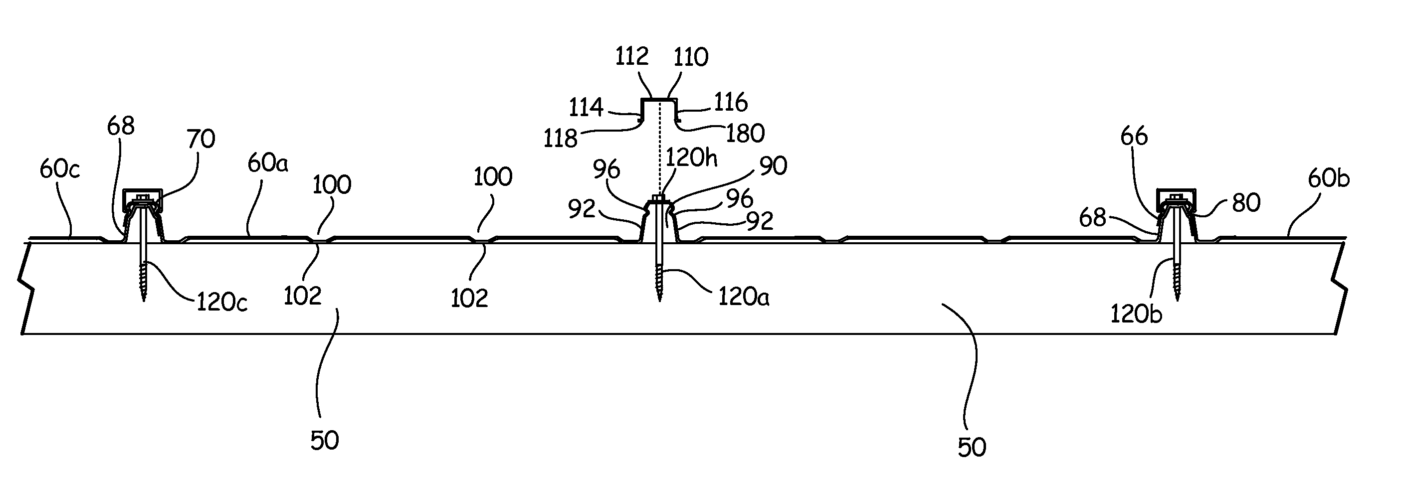
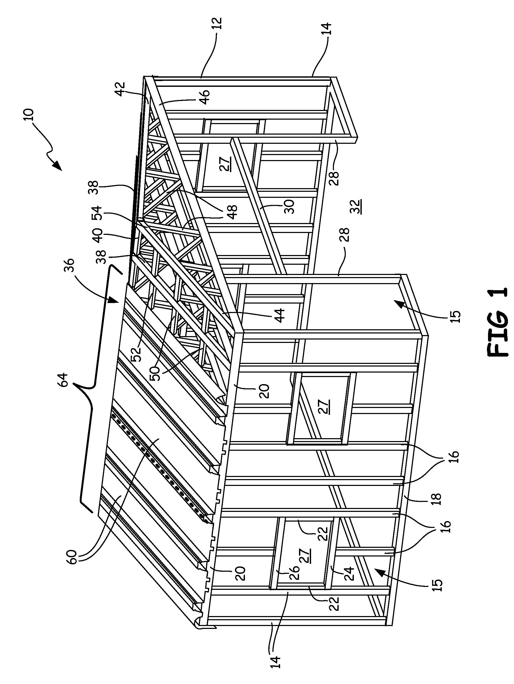
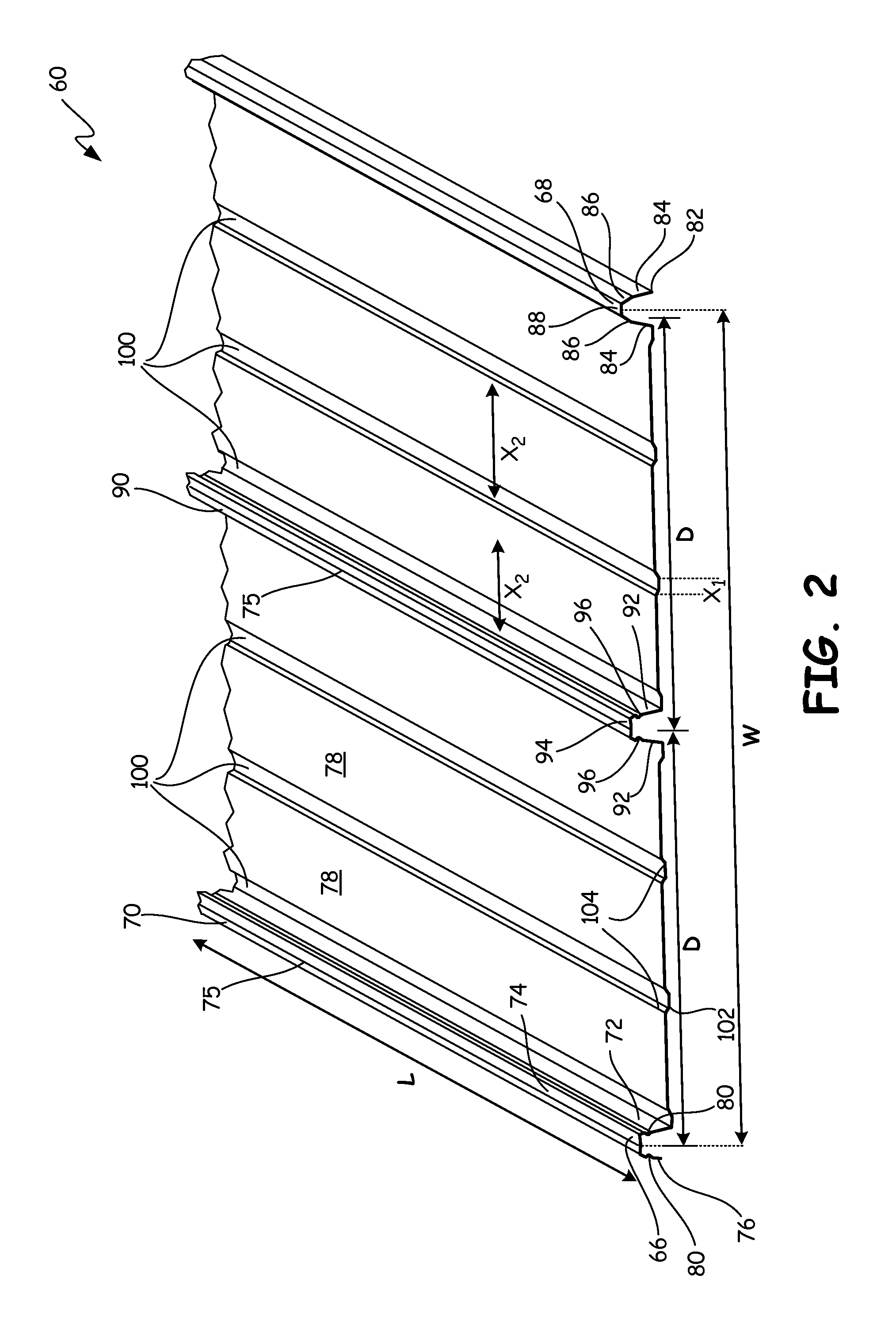
[0034]The roof industry has for decades searched for a panel that has the weathering and appearance characteristics of current standing-seam panels, and the bracing and diaphragm capacity inherent with through-fastened, concealed fastener panels. An exterior cladding panel assembly for covering an outside surface of a framed building is provided by the invention. A unique rib and batten system with overlapping raised female and male edge ribs on the adjacent installed panels, and raised interior ribs allow through fastening of the panels on the order of 32 inches or wider to the building's underlying framing structure with complete concealment of the fasteners, and without the need for special fastener clips. The ribs have an inverted U-shaped end profile that creates an open cavity between the rib top wall and the underlying framing member. The fastener can be driven through the rib top walls into the framing member without the need for a solid filler cleating strip. The lapping fe...


PUM


Abstract

An exterior cladding panel assembly for covering an outside surface of a framed building is provided by the invention. A unique rib and batten system with overlapping raised female and male edge ribs on the adjacent installed panels, and raised interior ribs allow through fastening of the panels on the order of 32 inches or wider to the building's underlying framing structure with complete concealment of the fasteners, and without the need for special fastener clips. The ribs have an inverted U-shaped end profile that creates an open cavity between the rib top wall and the underlying framing member. The fastener can be driven through the rib top walls into the framing member without the need for a solid filler cleating strip.

Description

FIELD OF THE INVENTION[0001]This application relates generally to exterior cladding panels for covering the roof or wall of a building, and more specifically to such a panel with the associated screw being fastened through the underlying building frame.BACKGROUND OF THE INVENTION[0002]All shelter buildings, whether they are houses or agricultural or commercial structures, must be strong, stable, and weather-resistant. Such structures are typically framed from an assembly of interconnected wood or metal members that define their walls and roof line. Vertical studs and horizontal base plates and header plates provide structure to the walls, while defining door and window openings. A series of rafters and purlins provide structure to the roof while defining its ridges and valleys. This roof can ultimately be covered by an appropriately decorative and weather-tight material like asphalt, wood or slate shingles, or clay tiles. Likewise, the walls can be covered by a suitably decorative o...

Claims


Application Information

Patent Timeline
Patent Type & Authority Patents(United States)
IPC IPC(8): E04D3/30E04B1/70E04B1/38E04B1/68E04F13/22
CPCE04B1/7038E04B1/38E04B1/6803E04F13/22E04C2/08E04C2/322E04D3/30E04D3/362E04D3/366E04D13/1585
Inventor BOOR, PAUL A.
Owner LESTER BUILDING SYST
Why Eureka
Try Eureka