Eureka AIR delivers breakthrough ideas for toughest innovation challenges, trusted by R&D personnel around the world.

High-frequency bandwidth amplifying circuit

a high-frequency bandwidth and amplifier circuit technology, applied in the field of integrated circuits, can solve the problems of increasing the loss of signal in the transmission media process, increasing the cost of equipment, so as to achieve the effect of simple structure, lower power loss, and higher gain bandwidth produ

Inactive Publication Date: 2015-09-08
IPGOAL MICROELECTRONICS (SICHUAN) CO LTD
View PDF7 Cites 0 Cited by
  • Summary
  • Abstract
  • Description
  • Claims
  • Application Information

AI Technical Summary

Benefits of technology

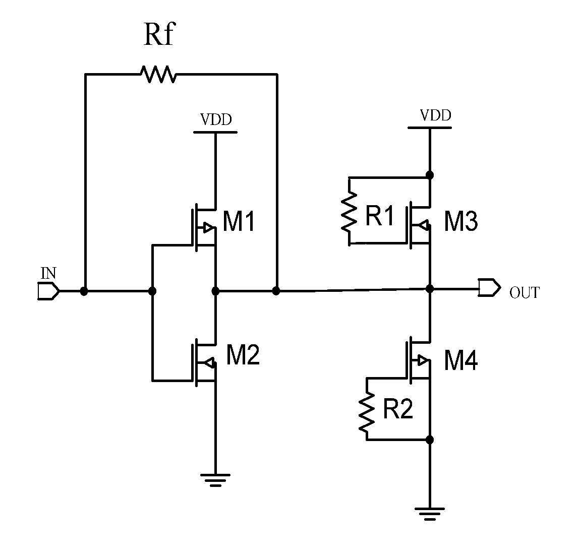
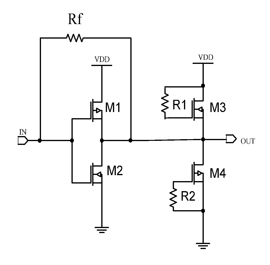
[0007]An object of the present invention is to provide a high-frequency bandwidth amplifier circuit. The high-frequency bandwidth amplifier circuit possesses a higher gain bandwidth product and lower power loss. A structure of a push-pull amplifier of the high-frequency bandwidth amplifier circuit is simple. A parasitic capacitance of the push-pull amplifier is small. And a noise is low.
[0017]Compared with the conventional technology, in the high-frequency bandwidth amplifier circuit of the present invention, because the output terminal of the push-pull amplifier is connected with the first active inductor and the second active inductor, the first end of the first active inductor is connected with the external power source, the first end of the second active inductor is grounded, so that the cooperation between the first inductor and the second inductor provides an extra zero that is able to offset a pole of the output terminal of the push-pull amplifier, to expend a bandwidth of an output signal, and to improve a gain bandwidth product of the output signal. The cooperation between the first active inductor and the second inductor makes “output-power source” and “output-ground”of the high-frequency bandwidth amplifier circuit appear in pairs, so an output working point of the push-pull amplifier is determined, a floating problem of the output working point of the push-pull amplifier is avoided, and a more balanced output driving is provided.

Problems solved by technology

Along with the higher and higher signal frequency, the loss of signal is also growing in the process of transmission media.
This method demands to provide larger current, and also demands for larger power loss, which makes this method more and more unattractive.
However, the current driving capability of the small-sized amplifier is also very weak, and thus the amplifier cannot satisfy working requirement.
Along with the further increased demand of the gain bandwidth product by the high-frequency bandwidth amplifier circuit, because of the limit of conventional topology, even if the current is further increased, the gain bandwidth product cannot be increased effectively.
Thus, the improvement of the gain bandwidth product by the high-frequency bandwidth amplifier circuit falls into technological bottlenecks.

Method used


Image

  • High-frequency bandwidth amplifying circuit
  • High-frequency bandwidth amplifying circuit

Examples


Embodiment Construction

[0021]Referring to the FIGURE, according to a preferred embodiment of the present invention is illustrated, wherein each element is represented by a corresponding designator. As mentioned above, the present invention provides a high-frequency bandwidth amplifier circuit. The high-frequency bandwidth amplifier circuit possesses a higher gain bandwidth product and lower power loss. A structure of a main operational amplifier of the high-frequency bandwidth amplifier circuit is simple. A parasitic capacitance is small. And a noise is low.

[0022]Referring to the FIGURE, the present invention provides a high-frequency bandwidth amplifier circuit, comprising:

[0023]a push-pull amplifier,

[0024]a feedback resistor Rf,

[0025]a first active inductor, and

[0026]a second active inductor,

[0027]wherein an input terminal of the push-pull amplifier is connected with an external input terminal IN. An output terminal of the push-pull amplifier is connected with an output port OUT. The push-pull amplifier...


PUM


Abstract

A high-frequency bandwidth amplifier circuit comprises: a push-pull amplifier, a feedback resistor, a first active inductor, and a second active inductor. An input terminal of the push-pull amplifier is connected with an external input terminal. An output terminal of the push-pull amplifier is connected with an output port. A first end of the feedback resistor is connected with the external input terminal. A second end of the feedback resistor is connected with the output port. A first end of the first active inductor is connected with an external power source. A second end of the first active inductor is connected with the output port. A first end of the second active inductor is grounded. A second end of the second active inductor is connected with the output port.

Description

BACKGROUND OF THE PRESENT INVENTION[0001]1. Field of Invention[0002]The present invention relates to the field of integrated circuit (IC), and more particularly to a high-frequency bandwidth amplifier circuit.[0003]2. Description of Related Arts[0004]In different kinds of signal receivers (RF communications, optical communications, high-speed serial communications), the weak signals received are required to be further amplified, in order to facilitate processing the weak signal by the follow-up circuit. Along with the higher and higher signal frequency, the loss of signal is also growing in the process of transmission media. It is well known that the higher signal frequency requires the wider bandwidth of the amplified circuit, and the higher loss of signal requires the higher gain of the amplified circuit. The combination of these two aspects demands for amplifiers of higher and higher gain bandwidth product.[0005]In the conventional high-frequency bandwidth amplifier circuit, basi...

Claims


Application Information

Patent Timeline
Patent Type & Authority Patents(United States)
IPC IPC(8): H03F3/26H03F3/30H03F3/195
CPCH03F3/195H03F3/3016H03F2200/294H03F2203/30031
Inventor ZHANG, ZICHE
Owner IPGOAL MICROELECTRONICS (SICHUAN) CO LTD
Why Eureka
Eureka Blog
Learn More