Signal stacking in fiber optic distributed acoustic sensing

a technology of distributed acoustic sensing and signal stacking, applied in seismic signal receivers, instruments, seismic fields, etc., can solve the problems of distributed acoustic systems, undesired low signal to noise ratio, and significant noise in systems, so as to improve the signal to noise ratio of das systems

Active Publication Date: 2015-09-22
SHELL USA INC
View PDF63 Cites 28 Cited by
  • Summary
  • Abstract
  • Description
  • Claims
  • Application Information

AI Technical Summary

Benefits of technology

[0011]The present invention improves the signal to noise ratio of a DAS system while maintaining the relatively low cost and simplicity of DAS hardware. In some embodiments, the present invention includes a method for obtaining information about a subsurface formation from acoustic signals that contain information about the subsurface formation by a) transmitting an optical signal into a fiber optic cable that includes a sensing apparatus comprising a plurality of substantially parallel fiber lengths; b) collecting from the sensing apparatus a plurality of received optical signals, each received signal comprising a portion of the transmitted signal that has been reflected from a segment of a different fiber length, wherein the different segments correspond to a single selected position along the sensing apparatus; and c) processing the collected signals so as to obtain information about an acoustic signal received at the different segments.

Problems solved by technology

While there exists a variety of commercially available DAS systems that have varying sensitivity, dynamic range, spatial resolution, linearity, etc., these systems tend to have an undesirably low ratio of signal to noise.
In addition, it has been discovered that distributed acoustic systems, particularly those that rely on Rayleigh backscattering are subject to significant noise and that the noise is random or statistical in nature.
This technique is disadvantageous, however, because it requires more complex data processing and optical components than a single-pulse system.

Method used


Image

  • Signal stacking in fiber optic distributed acoustic sensing
  • Signal stacking in fiber optic distributed acoustic sensing

Examples


Embodiment Construction

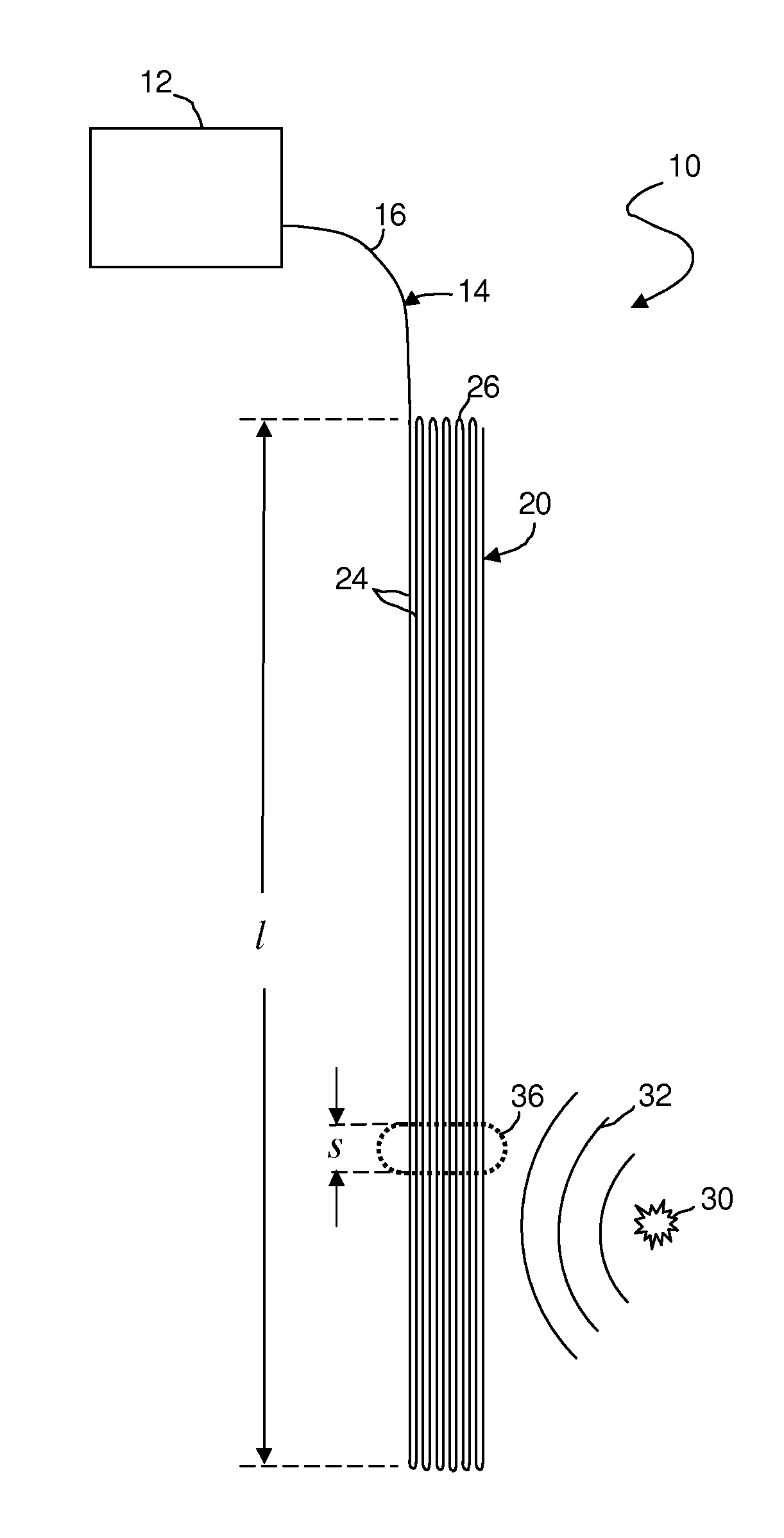
[0017]Referring to the FIGURE, a system 10 according to a preferred embodiment of the invention comprises a light box 12 and a fiber optic cable 14. Light box 12 comprises a light source and an optical receiver (not shown). Fiber optic cable 14 comprises an optional lead-in cable 16 and a sensing apparatus 20. If lead-in cable 16 is not present, sensing apparatus 20 may be connected directly to light box 12. Sensing apparatus 20 preferably comprises a plurality of n lengths of fiber 24, each length of fiber 24 having a length l, with adjacent pairs of fibers connected in series at fiber ends 26 so as to form an effective cable length L, where L=n×l.

[0018]One preferred embodiment of sensing apparatus 20 comprises one or more lengths of un-armored, dielectric-coated ribbon cable, such as SST-ribbon cable, such as is inexpensive and commercially available from Corning Cable Systems of Hickory, NC or from AFL Telecommunications of Duncan, S.C. Preferred ribbon cables contain 6-24 optica...


PUM


Abstract

A method for obtaining information about a subsurface formation from acoustic signals that contain information about the subsurface formation, comprises a) transmitting an optical signal into a fiber optic cable (14) that includes a sensing apparatus (20) comprising a plurality of substantially parallel fiber lengths (24), b) collecting from the sensing apparatus a plurality of received optical signals, each received signal comprising a portion of the transmitted signal that has been reflected from a different segment of a cable length, wherein the different segments are each in different cable lengths and correspond to a single selected location along the sensing cable, and c) processing the collected signals so as to obtain information about an acoustic signal received at the different segments. The cable may be ribbon cable and the lateral distance between the different segments may be less than 10 meters.

Description

RELATED CASES[0001]The present application claims priority from PCT / US2011 / 041324, filed 22 Jun. 2011, which claims priority from U.S. provisional application 61 / 358,672, filed 25 Jun. 2010, which are both incorporated herein by reference.FIELD OF THE INVENTION[0002]The invention relates to a method of increasing the signal to noise ratio of an optical acoustic sensing system by sensing and stacking signals from a plurality of sections of optical fiber.BACKGROUND OF THE INVENTION[0003]Various attempts have been made to provide sensing capabilities in the context of petroleum exploration, production, and monitoring, with varying degrees of success.[0004]Recently, these attempts have included the use of fiber optic cables to detect acoustic energy. Because the cables typically comprise optically conducting fiber containing a plurality of backscattering inhomogeneities along the length of the fiber, such systems allow the distributed measurement of axial strain along an optical fiber b...

Claims


Application Information

Patent Timeline
Patent Type & Authority Patents(United States)
IPC IPC(8): G01V1/48G01V1/16
CPCG01V1/48G01V1/16
Inventor LOPEZ, JORGE LOUISPOTTERS, JOHANNES HUBERTUS HYACINTHUS MARIAWILLS, PETER BERKELEY
Owner SHELL USA INC
Why Eureka
Try Eureka