Fiber fault detection within data transceiver having micro OTDR (μOTDR) for fiber optic network

a technology of fiber optic network and data transceiver, which is applied in the direction of electromagnetic transceivers, transmission monitoring, testing of fibre optic/optical waveguide devices, etc., can solve the problems of spike power, difficult to maintain constant observation and monitoring, and fences and other structures

Active Publication Date: 2015-09-22
OPTICAL ZONU CORP
View PDF24 Cites 27 Cited by
  • Summary
  • Abstract
  • Description
  • Claims
  • Application Information

AI Technical Summary

Benefits of technology

[0031]It is still another object of the present invention to provide for an optical fiber fault detector that measures the exact link distance during installation without having to previously map out the entire fiber optic network.
[0032]It is s

Problems solved by technology

The same can be done for fences and other structures that are long and are otherwise difficult to maintain constant observation and monitoring.
The reason for the minute change is the instantaneous interference that can actually spike the power when two flat optical terminations ar

Method used


Image

  • Fiber fault detection within data transceiver having micro OTDR (μOTDR) for fiber optic network
  • Fiber fault detection within data transceiver having micro OTDR (μOTDR) for fiber optic network
  • Fiber fault detection within data transceiver having micro OTDR (μOTDR) for fiber optic network

Examples


Embodiment Construction

[0051]Although specific embodiments of the present invention will now be described with reference to the drawings, it should be understood that such embodiments are by way of example only and merely illustrative of but a small number of the many possible specific embodiments which can represent applications of the principles of the present invention. Various changes and modifications obvious to one skilled in the art to which the present invention pertains are deemed to be within the spirit, scope and contemplation of the present invention as further defined in the appended claims.

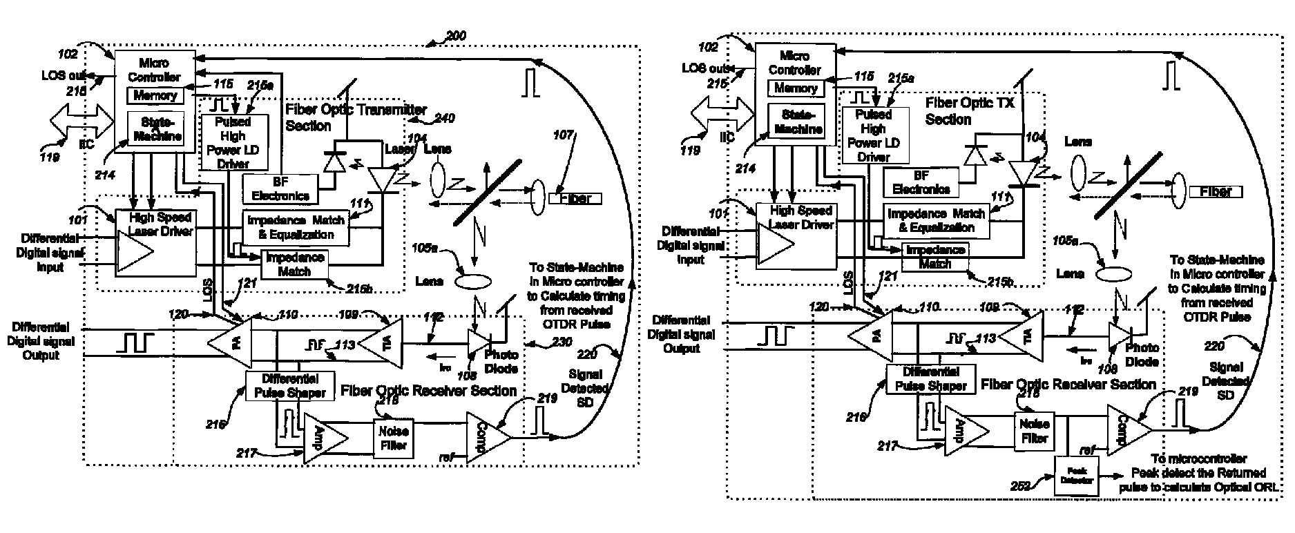
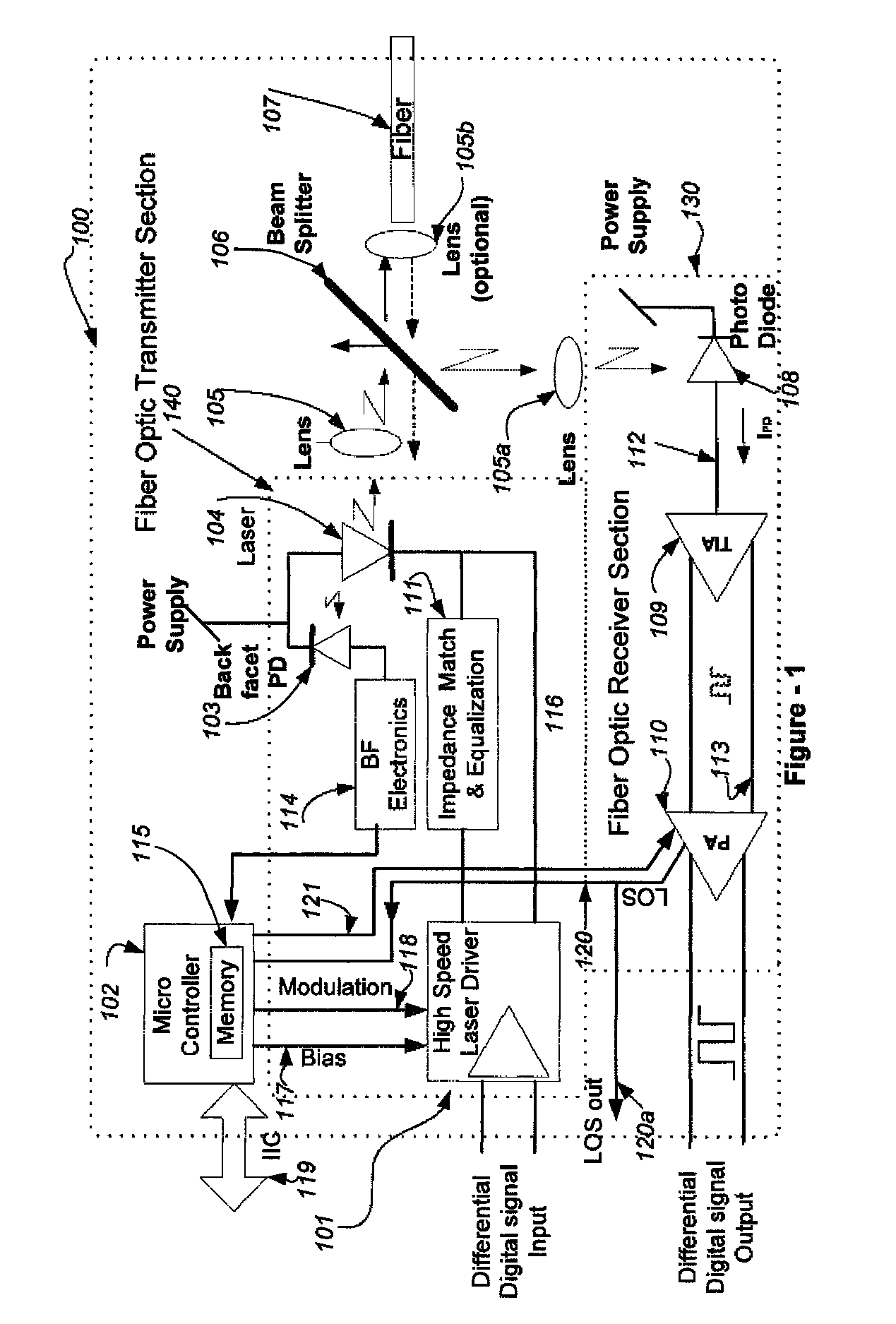
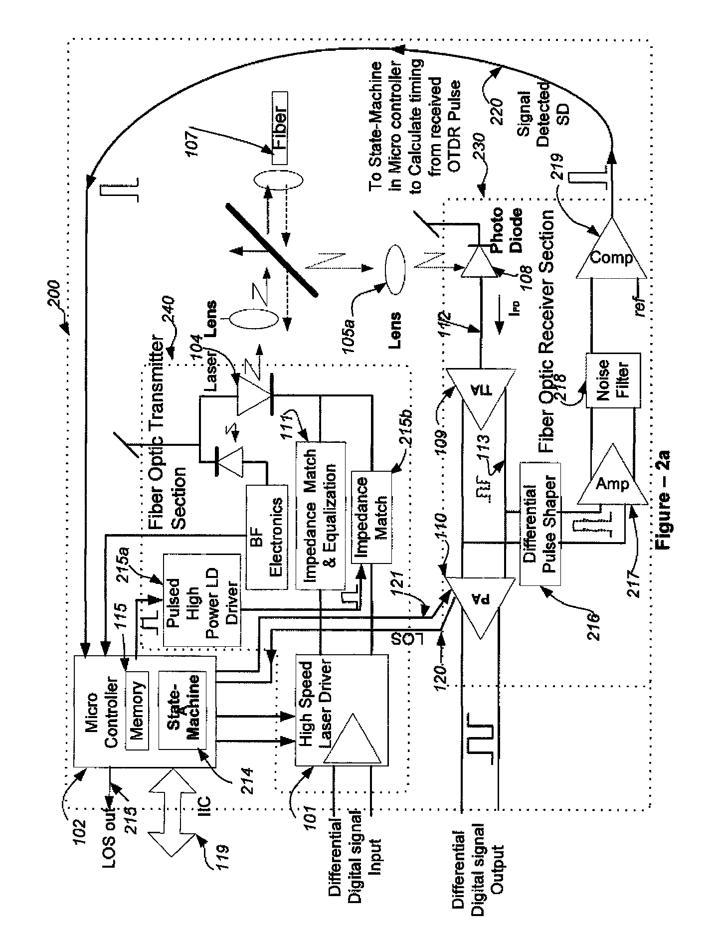
[0052]Referring now to FIG. 1, there is shown a block diagram of a BI-DIRECTIONAL TRANSCEIVER 100. The TRANSCEIVER 100 is generally divided in two, having a FIBER OPTIC RECEIVER SECTION 130 and a FIBER OPTIC TRANSMITTER SECTION 140.

[0053]In general, a standard, single fiber, single wavelength fiber optic bi-directional TRANSCEIVER 100 has the following main functional elements:

[0054]A Digital Laser Diode (...


PUM


Abstract

The present invention is an apparatus and method that identifies and localizes fiber breaks or faults automatically, utilizing a fiber optic data transceiver that has μOTDR functionality. The transceiver of the present invention is a single wavelength bi-directional transceiver that during normal operation sends and receives optical data streams in the same wavelength window using any protocol and reports the distance to the fault or multiple faults nearly instantaneously when the transfer of data is disrupted, without the need to have fiber lines dedicated for this purpose or physically connect and reconnect each fiber line to check for faults and eliminates the need to map out the distance to the remote transceiver.

Description

[0001]This patent application claims priority to Provisional Application Ser. No. 61 / 521,311 filed on Aug. 8, 2011.BACKGROUND OF THE INVENTION[0002]1. Field of the Invention[0003]The present invention relates to the detection of faults within a fiber optic network and the determination of the location of the detected fault and more specifically to the method and apparatus to determine the presence of, and location of, a fiber network fault, within a single optical fiber strand, utilizing, in particular, a transceiver that operates as both a digital bi-directional data transport on the same fiber, and a micro optical time-domain reflectometer (μOTDR).[0004]2. Description of the Prior Art[0005]In general terms, the detection of communication line faults has been a concern in the art for a long time. The advent of the communication age was accompanied by the proliferation of the necessary wires and cables to support that communication. As the communication networks grew larger, so too ...

Claims


Application Information

Patent Timeline
IPC IPC(8): H04B10/50H04B17/00H04B10/40
CPCH04B10/504H04B10/40H04B10/071G01M11/3145
Inventor BARTUR, MEIRSTEPHENSON, JIMGHADOOSHAHY, FARZAD
Owner OPTICAL ZONU CORP
Why Eureka
Try Eureka