Intake system with an integrated charge air cooler

a technology of air cooler and inlet system, which is applied in the direction of air intakes for fuel, combustion air/fuel air treatment, machines/engines, etc., can solve the problems of reducing the compactness of the induction system, negatively affecting torque response, packaging and egr control, and increasing losses within such an induction system, so as to increase the power output of the engine, reduce the emission of the engine, and increase the pressure in the combustion chamber

Active Publication Date: 2015-09-29
FORD GLOBAL TECH LLC
View PDF13 Cites 18 Cited by
  • Summary
  • Abstract
  • Description
  • Claims
  • Application Information

AI Technical Summary

Benefits of technology

[0002]Many engines utilize compressors in the intake system to provide boost to the engine to increase the pressure in the combustion chamber, thereby increasing the power output of the engine. Some engines also utilize an exhaust gas recirculation (EGR) loop to reduce emission from the engine and / or improve fuel economy. The EGR loop can be either “high pressure” (HP) where the EGR is taken before the turbine and injected after the compressor, or “low pressure” (LP) where the EGR is taken after the turbine and injected before the compressor. For both scenarios, the compressor and the EGR loop increase the temperature of the intake air provided to the cylinders, thereby reducing the density of the air provided to the cylinder. As a result, the combustion efficiency is decreased. To decrease the temperature of the intake air charge air coolers may be positioned in the intake system. In some engines, the charge air cooler may be positioned in a conduit downstream of the compressor and upstream of a throttle as part of the front end cooling module as the charge air cooler is typically air cooled. In other applications, the charge air cooler may be water cooled and mounted in the engine compartment.
[0003]The inventors of the present application have recognized a problem in such previous solutions. First, to accommodate the charge air cooler in the pre-throttle position, the volume of the induction system is increased, thereby decreasing the compactness of the induction system and negatively impacting torque response, packaging and EGR control. This is especially true if the charge air cooler is located in the front cooling module, as it is typical for the charge air cooler to be cooled by outside air. Moreover, losses within such an induction system are increased when the size of the system is increased. Additionally, this large throttled volume negatively impacts EGR control. LP EGR suffers from large transport delays negatively affecting its control and ability to improve fuel economy and reduce emissions in the engine. Because HP EGR is typically introduced in the intake manifold, the aforementioned arrangement does not permit the HP EGR to traverse the charge air cooler, reducing its cooling level and ability to improve fuel economy and emissions and not negatively impacting combustion efficiency.
[0004]Accordingly, in one example, some of the above issues may be addressed by an intake assembly in an engine. The intake assembly includes a compressor and a plenum in fluidic communication with the compressor, the plenum having an integrated charge air cooler. The charger air cooler may include a coolant inlet and a coolant outlet in fluidic communication with a coolant passage and cooling plates extending into a plenum enclosure and coupled to the coolant passage. Thus, the charger air cooler may be water cooled. The intake assembly further includes a throttle body coupled to the plenum positioned after the integrated charge air cooler. Such an arrangement allows for the benefits of an integrated charge air cooler without unacceptably increasing “throttled volume”, which is detrimental to drivability and engine responsiveness. When the charge air cooler is integrated into an intake plenum the throttle volume is reduced, when compared to intake system having a charge air cooler positioned in a separate enclosure. Furthermore, the integration of the charger air cooer into the plenum enables the overall compactness of the intake system may be increased while providing charge air cooling to intake air, avoiding the charge air heating via operation of a compressor or EGR gas delivered to the intake system. As a result, the density of the air provided to the cylinders in the engine is increased, enabling the combustion efficiency to be increased without increasing the overall size of the intake assembly. A portion of the charge air cooler may be positioned in an enclosure of the plenum, thereby reducing the increase in size of the intake assembly when the charge air cooler is integrated into the assembly. Furthermore, the reduction to boosted volume allows for better control of LP EGR, improved cooling of HP EGR as it now traverses the charge air cooler and improved throttle response as the throttle is now located downstream of the main intake plenum and throttled volume is reduced.

Problems solved by technology

First, to accommodate the charge air cooler in the pre-throttle position, the volume of the induction system is increased, thereby decreasing the compactness of the induction system and negatively impacting torque response, packaging and EGR control.
Moreover, losses within such an induction system are increased when the size of the system is increased.
Additionally, this large throttled volume negatively impacts EGR control.
LP EGR suffers from large transport delays negatively affecting its control and ability to improve fuel economy and reduce emissions in the engine.
Because HP EGR is typically introduced in the intake manifold, the aforementioned arrangement does not permit the HP EGR to traverse the charge air cooler, reducing its cooling level and ability to improve fuel economy and emissions and not negatively impacting combustion efficiency.
Such an arrangement allows for the benefits of an integrated charge air cooler without unacceptably increasing “throttled volume”, which is detrimental to drivability and engine responsiveness.

Method used


Image

  • Intake system with an integrated charge air cooler
  • Intake system with an integrated charge air cooler
  • Intake system with an integrated charge air cooler

Examples


Embodiment Construction

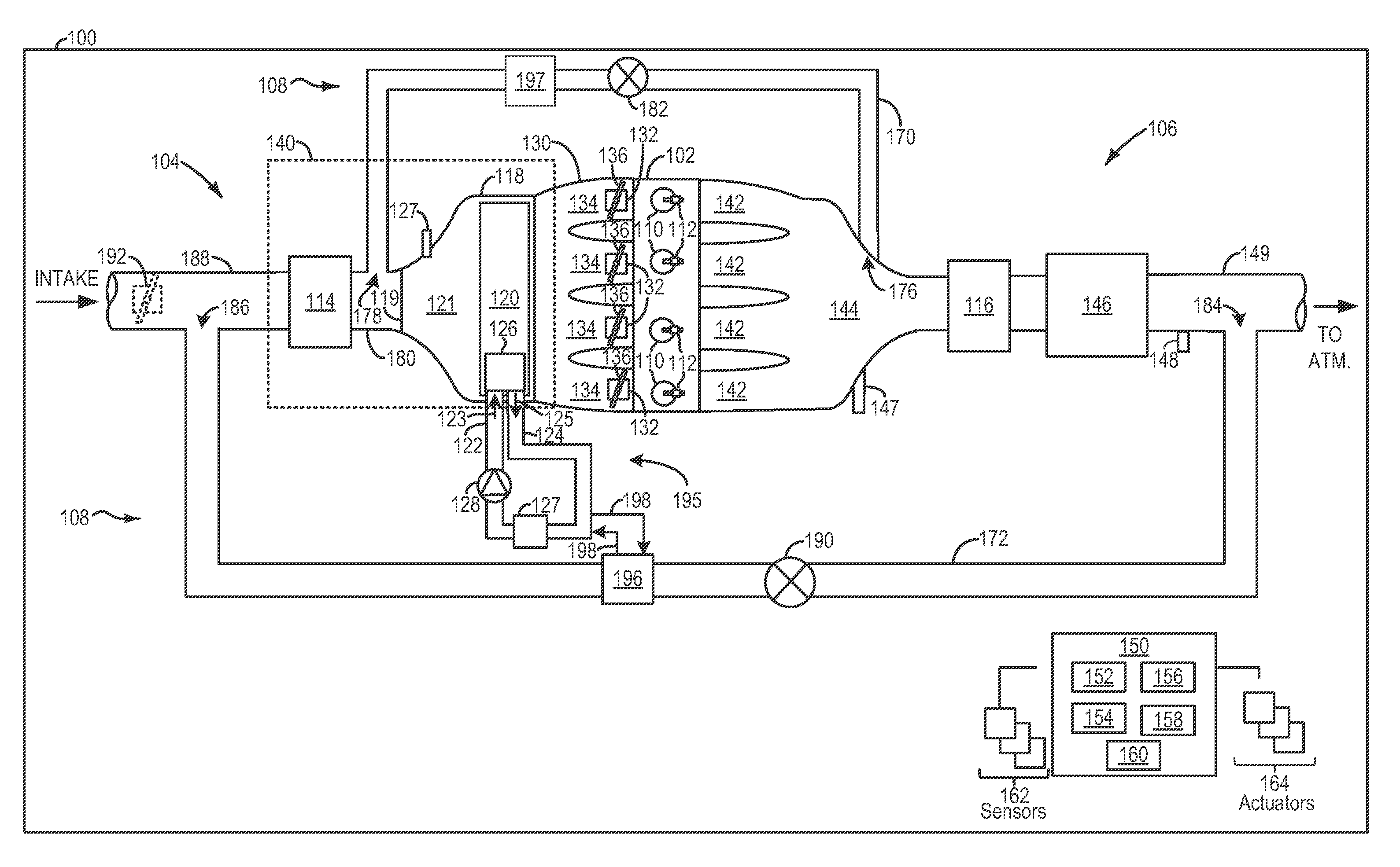
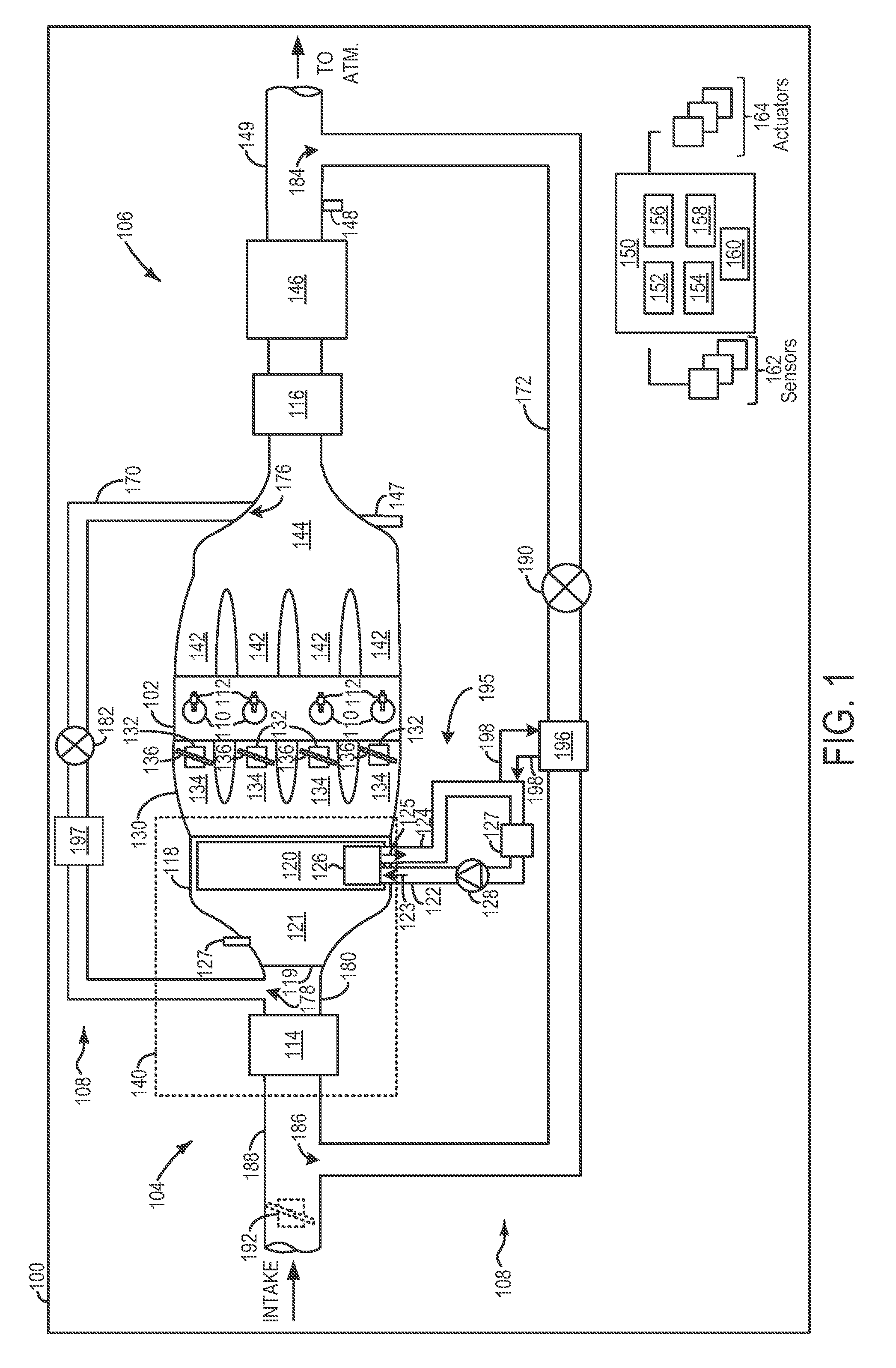
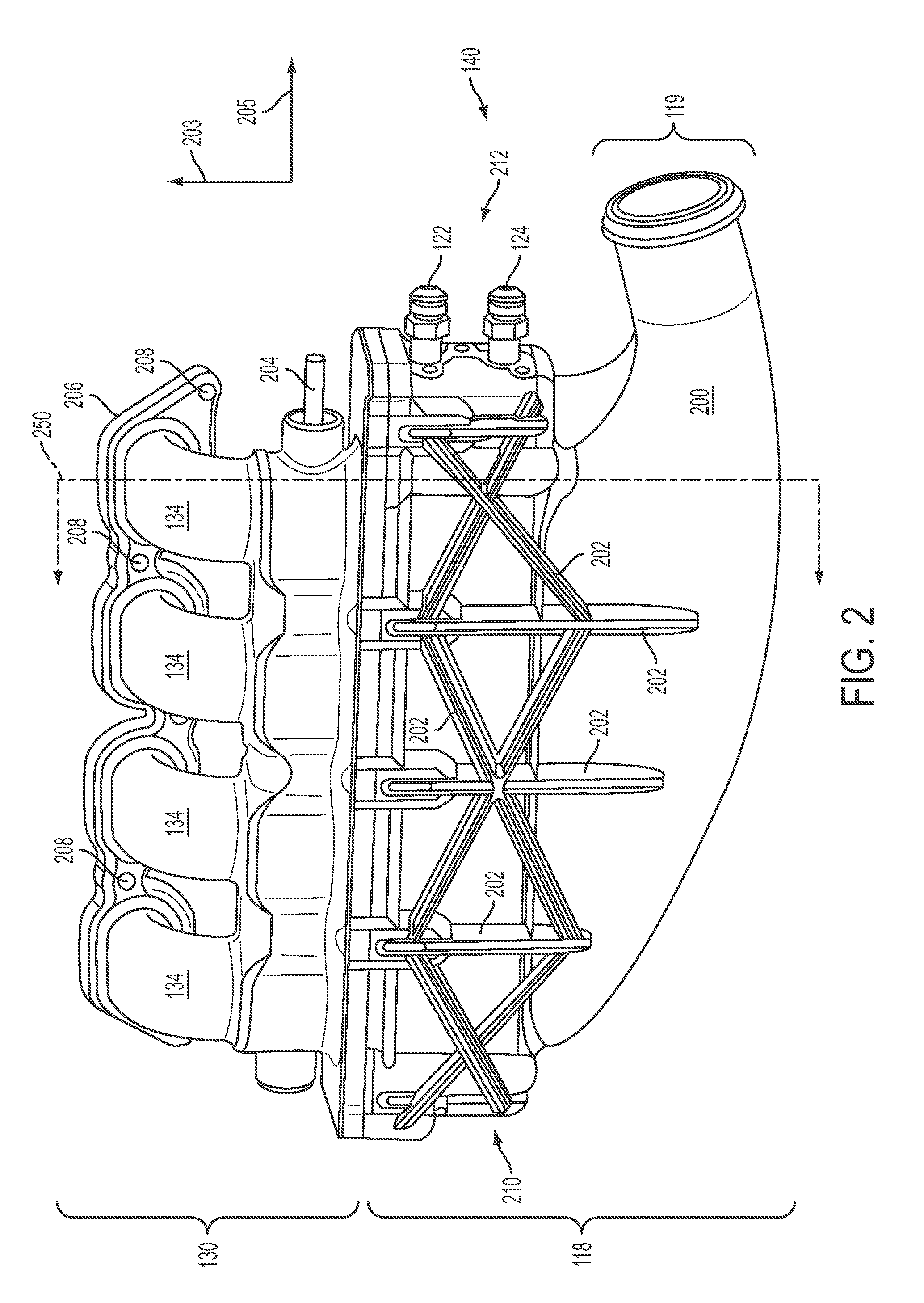
[0009]Embodiments of an intake assembly having a charge air cooler integrated into a plenum are described herein. The intake assembly includes a plenum coupled to a throttle body, the plenum having a housing defining a plenum enclosure. Cooling plates in the charge air cooler extend across the plenum enclosure. When the charge air cooler is integrated into the plenum, the compactness of the intake system is increased while providing charge air cooling to intake air which may be heated via operation of a compressor or EGR gas delivered to the intake system upstream of the plenum. Thus, the charge air cooler enables the boosted volume provided to the engine to be reduced. The reduction in boosted volume enables combustion efficiency to be increased. Furthermore, the reduction to boosted volume allows for better control of a low pressure (LP) exhaust gas recirculation (EGR), if desired.

[0010]Moreover, the throttle volume of the intake system is reduced when the charger air cooler is in...


PUM


Abstract

An intake assembly in an engine is provided. The intake assembly includes a compressor and a plenum in fluidic communication with the compressor, the plenum having an integrated charge air cooler including a coolant inlet and a coolant outlet in fluidic communication with a coolant passage and cooling plates extending into a plenum enclosure and coupled to the coolant passage. The intake assembly further includes a throttle body coupled to the plenum.

Description

TECHNICAL FIELD[0001]The present application relates an intake system with an integrated charge air cooler in an intake system.BACKGROUND AND SUMMARY[0002]Many engines utilize compressors in the intake system to provide boost to the engine to increase the pressure in the combustion chamber, thereby increasing the power output of the engine. Some engines also utilize an exhaust gas recirculation (EGR) loop to reduce emission from the engine and / or improve fuel economy. The EGR loop can be either “high pressure” (HP) where the EGR is taken before the turbine and injected after the compressor, or “low pressure” (LP) where the EGR is taken after the turbine and injected before the compressor. For both scenarios, the compressor and the EGR loop increase the temperature of the intake air provided to the cylinders, thereby reducing the density of the air provided to the cylinder. As a result, the combustion efficiency is decreased. To decrease the temperature of the intake air charge air c...

Claims


Application Information

Patent Timeline
Patent Type & Authority Patents(United States)
IPC IPC(8): F02M25/07F02M35/10F02M35/112F02B29/04F02D9/10F02D21/08
CPCF02M35/10255F02B29/0443F02B29/0462F02B29/0475F02D9/1095F02D21/08F02M25/0707F02M25/0709F02M35/10052F02M35/10268F02M35/112F02M25/0731F02M25/0732Y02T10/121Y02T10/14Y02T10/146F02M26/05F02M26/06F02M26/28F02M26/24Y02T10/12
Inventor MACERONI, KAREN ELIZABETHWICKS, CHRIS DONALDSTYLES, DANIEL JOSEPHMADIN, MARK MICHAELWILLIAMS, RICK L.
Owner FORD GLOBAL TECH LLC
Why Eureka
Try Eureka