
Metal insulator metal capacitor and method for making the same

a metal capacitor and metal insulator technology, applied in capacitors, semiconductor/solid-state device testing/measurement, semiconductor/solid-state device details, etc., can solve the problems of increasing the size and complexity of the circuit, the noise of the power supply line, and the fluctuation of the voltage on the power supply lin

Active Publication Date: 2015-10-06
TAIWAN SEMICON MFG CO LTD
View PDF7 Cites 9 Cited by
  • Summary
  • Abstract
  • Description
  • Claims
  • Application Information

AI Technical Summary

Benefits of technology

The patent text describes various embodiments and methods for integrating decoupling capacitors into semiconductor integrated circuits (ICs). These capacitors are used to prevent fluctuations in power supply voltage and can help improve the stability and functionality of the circuit. However, there are some challenges in integrating these capacitors, such as variations in capacitance and delamination of conductors. The patent text provides various solutions to these challenges and provides different types of decoupling capacitors that can be used in ICs.

Problems solved by technology

Technological advances in semiconductor materials and design have produced increasingly smaller and more complex circuits.
These conditions can result in noise on the power supply lines.
Specifically, the voltage on the power supply line may fluctuate when the transition time of the transient current is particularly short or when the line's parasitic inductance or parasitic resistance is large.
Integrating decoupling capacitors into certain systems-on-chip (SOCs) may entail a number of problems.
For example, some decoupling capacitors may suffer from capacitance variations, delamination of conductors from the electrodes, or inadequate electrical coupling between the conductor and the electrodes.

Method used


Image

  • Metal insulator metal capacitor and method for making the same
  • Metal insulator metal capacitor and method for making the same
  • Metal insulator metal capacitor and method for making the same

Examples


Embodiment Construction

[0014]It is to be understood that the following disclosure provides many different embodiments and examples for implementing different features of the invention. Specific examples of components and arrangements are described below to simplify the present disclosure. These are, of course, merely examples and are not intended to be limiting. Moreover, the formation of a first feature over or on a second feature in the description that follows may include embodiments in which the first and second features are formed in direct contact, and may also include embodiments in which additional features may be formed interposing the first and second features, such that the first and second features may not be in direct contact. Various features in the figures may be arbitrarily drawn in different scales for the sake of simplicity and clarity.

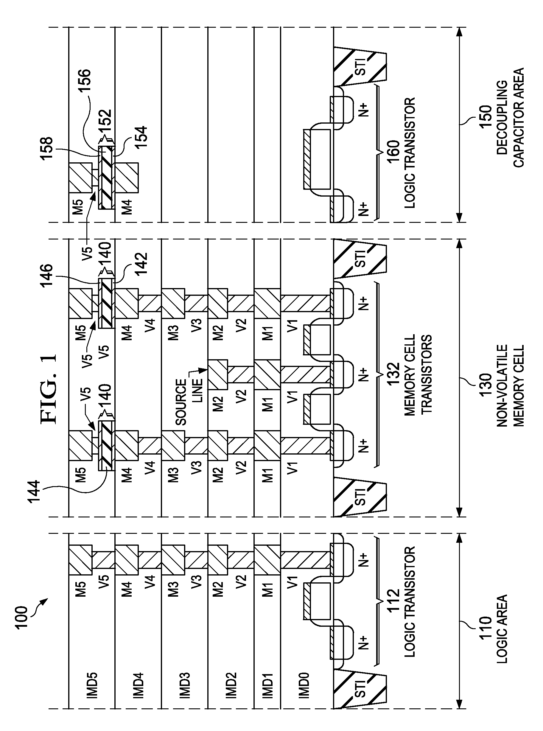
[0015]FIG. 1 illustrates a system-on-chip (SOC) 100, which may include a plurality of functional areas fabricated on a single substrate. As depicted in FI...


PUM


Abstract

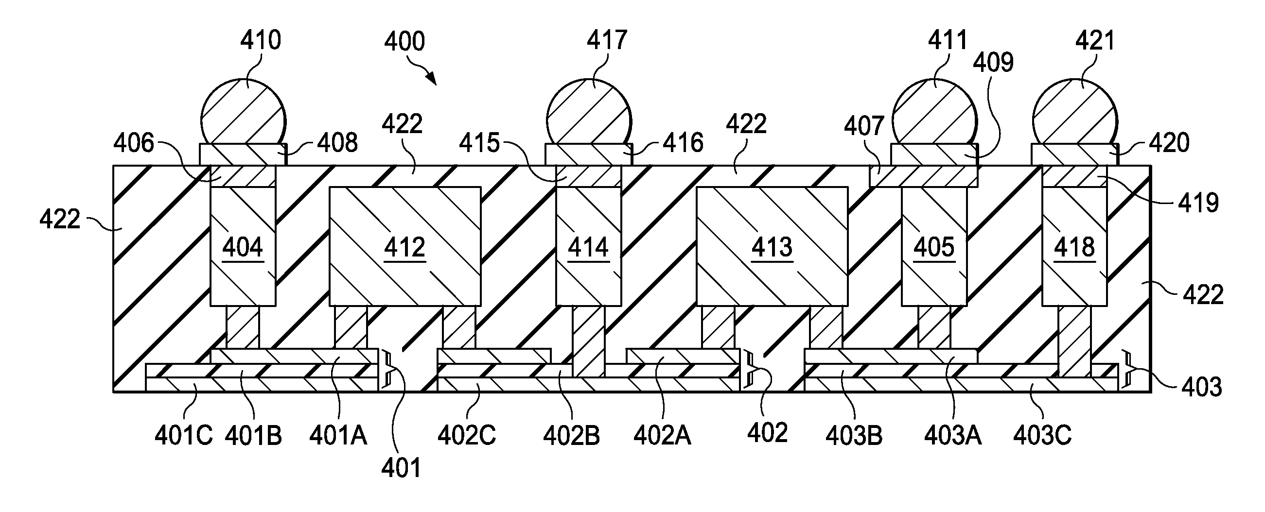
A semiconductor device includes one or more metal-insulator-metal (MiM) capacitors. The semiconductor device includes a bottom electrode, a dielectric layer located above, and in physical contact with, the bottom electrode, a top electrode located above, and in physical contact with, the dielectric layer, a first top contact contacting the top electrode, a first bottom contact contacting the bottom electrode from a top electrode direction, a first metal bump connecting to the top contact, and a second metal bump connecting to the bottom contact. The top electrode has a smaller area than the bottom electrode. The bottom electrode, the dielectric layer, and the top electrode is a MiM capacitor. Top electrodes of a number of MiM capacitors and bottom electrodes of a number of MiM capacitors are daisy chained to allow testing of the conductivity of the electrodes.

Description

BACKGROUND[0001]The semiconductor integrated circuit industry has experienced rapid growth in the past several decades. Technological advances in semiconductor materials and design have produced increasingly smaller and more complex circuits. These material and design advances have been made possible as the technologies related to processing and manufacturing have also undergone technical advances. In the course of semiconductor evolution, the number of interconnected devices per unit of area has increased as the size of the smallest component that can be reliably created has decreased.[0002]Metal-insulator-metal (MiM) capacitors are used in many applications on an integrated circuit (IC), including for signal conditioning. During the operation of certain circuits, power supply lines may supply transient currents with a relatively high intensity. These conditions can result in noise on the power supply lines. Specifically, the voltage on the power supply line may fluctuate when the ...

Claims


Application Information

Patent Timeline
IPC IPC(8): H01L21/02H01L21/66H01L49/02H01L23/58H01L27/108
CPCH01L22/14H01L28/40H01L28/60H01L21/768H01L22/32H01L22/34H01L2924/181
Inventor LAI, YU-CHIASHAO, TUNG-LIANGYANG, CHING-JUNG
Owner TAIWAN SEMICON MFG CO LTD
Learn More