Optical signal processing with modelocked lasers

a laser mode and optical signal technology, applied in the field of optical signal processing to modelocked lasers, can solve the problems of slow data acquisition rate, limited widespread use of frequency comb lasers, and limited resolution of this scheme, so as to improve the signal/noise ratio of a fts, improve the resolution and improve the sensitivity of a fts based on cdsl

Inactive Publication Date: 2015-10-06
IMRA AMERICA
View PDF76 Cites 8 Cited by
  • Summary
  • Abstract
  • Description
  • Claims
  • Application Information

AI Technical Summary

Benefits of technology

[0017]Various high resolution CDSL embodiments include first and second mode locked oscillators operated at slightly different repetition rates, each mode locked oscillator having a carrier envelope offset frequency. Outputs of the first and second mode locked oscillators, in combination with outputs from two reference lasers, are used to generate signals for stabilizing differences between both the carrier envelope offset frequencies and differences between the repetition rates of the two mode locked oscillators. In some embodiments the carrier envelope offset frequency of at least one oscillator may also be derived from the signals, resulting in a resolution corresponding to at least the bandwidth of the reference lasers and further allowing for Hertz level frequency resolution.
[0018]Various high resolution CDSLs are useable in systems for phase, absorption, emission and / or spectral measurement. Various embodiments provide high resolution FTS by utilizing a combination of optical phase-locking with optical referencing. In at least one embodiment the difference frequencies of two next neighbor comb lines from two mode locked lasers are phase-locked with at least two phase-locked loops using two cw reference lasers. Alternatively, frequency locking schemes can also be implemented. Tracking of the beat frequencies of the two cw reference lasers with the individual comb lines further allows absolute frequency calibration of the FTS. Various embodiments provide high resolution FTS by recording multiple adjacent interferograms, which increases the resolution of a FTS proportional to the signal acquisition time.
[0023]Emission spectral measurements can be used for the measurement of spontaneous and stimulated Raman emission spectra from optical samples, enhancement of Raman emission can further be implemented for improved signal / noise ratios and optical imaging and optical scanning can be implemented for the measurement of spatially resolved Raman spectra.
[0029]In at least one embodiment the resolution of a FTS based on CDSL is increased proportional to the signal acquisition time by minimizing fluctuations of the effective scan rate during the signal acquisition time.
[0030]In at least one embodiment dual balanced detection improves the signal / noise ratio of a FTS.

Problems solved by technology

Indeed, a difficulty limiting the widespread use of frequency comb lasers is precision optical phase-locking of the individual comb lines to at least two external reference frequencies in order to obtain a stable frequency comb.
However, when applied to Fourier transform absorption spectroscopy, the resolution of this scheme is also limited to the repetition rate of the mode locked lasers, assuming for example that a reference laser is located in between two comb lines and the absolute frequency of the reference laser or the absolute order m of the comb lines is not known.
As a result, relatively low repetition rate lasers are implemented which leads to slow data acquisition rates.

Method used


Image

  • Optical signal processing with modelocked lasers
  • Optical signal processing with modelocked lasers
  • Optical signal processing with modelocked lasers

Examples


Embodiment Construction

[0069]Some examples of CDSL systems and applications are disclosed below. Implementations providing for one or more of high resolution, high acquisition rate, high sensitivity, low-noise, and a high-level of integration are described. Non-linear spectral generation and various implementations for phase-control lead to stable output signals in the near-IR range, thereby providing benefits for IR absorption and emission spectroscopy, THz imaging and ranging applications.

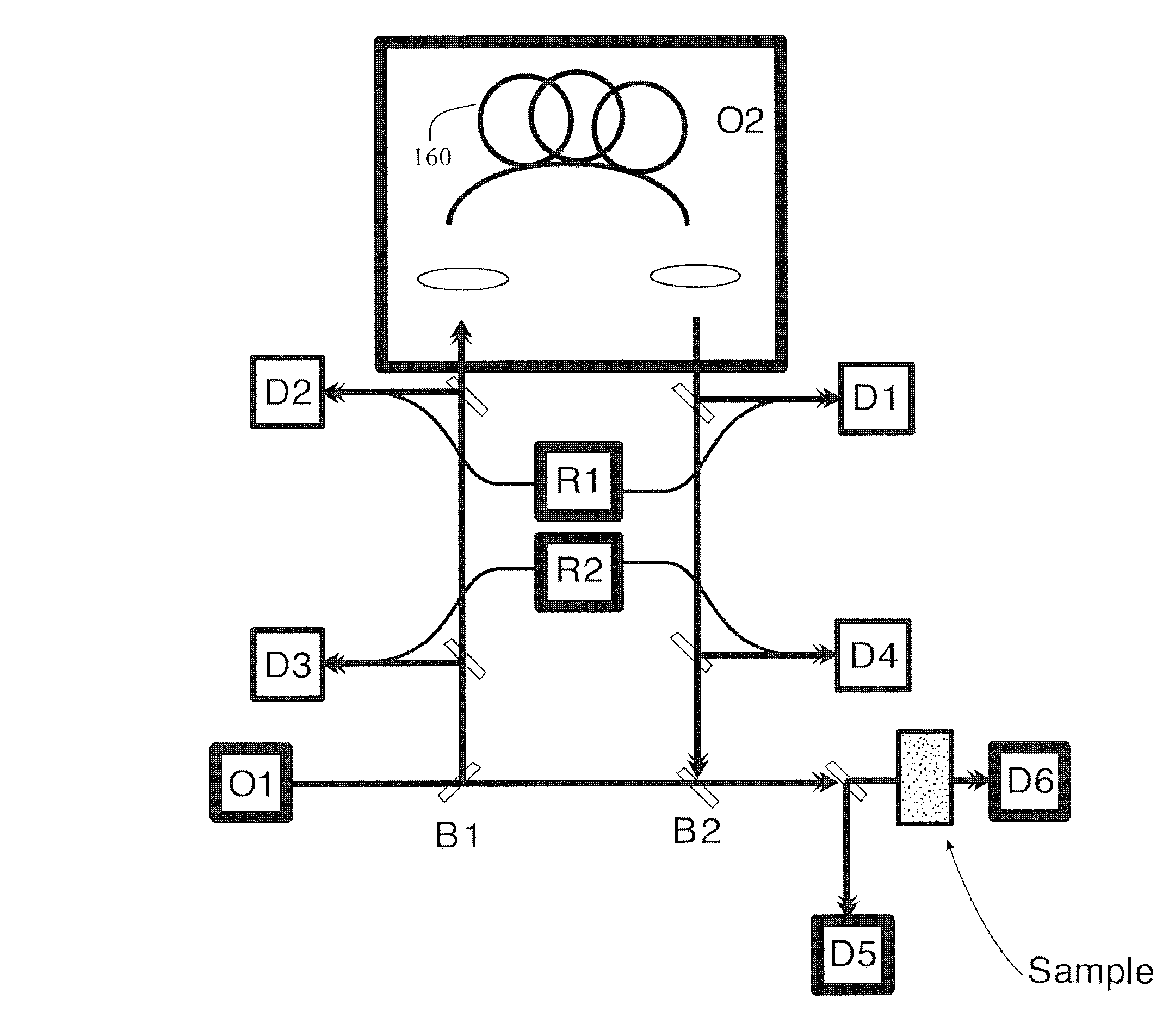
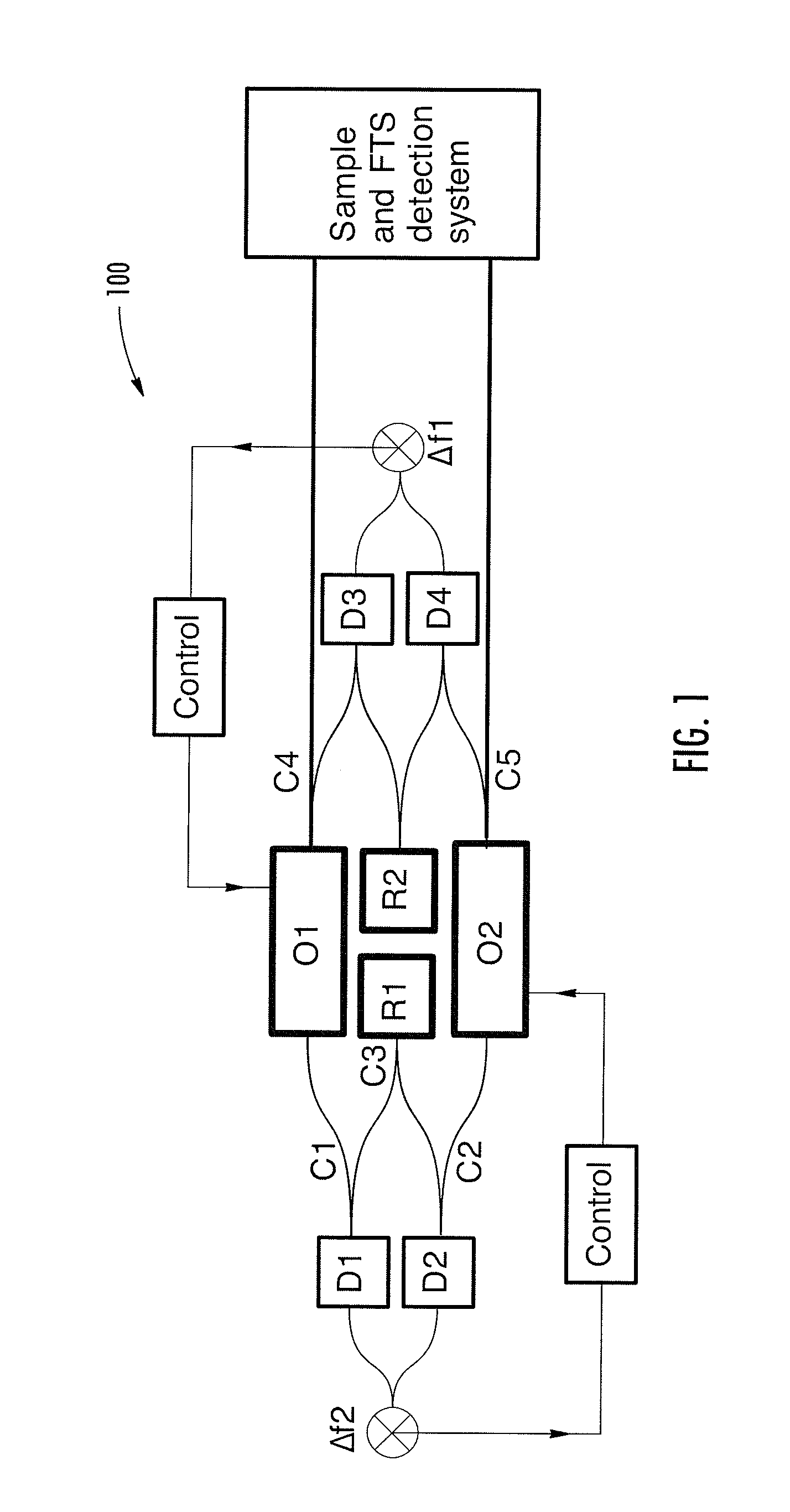
[0070]FIG. 1 schematically illustrates a coherent dual scanning laser system 100 (CDSL) according to an embodiment for Fourier transform absorption spectroscopy. In this example, output of CDSL 100 is directed to a sample to be measured. A Fourier transform spectrometer (FTS) probes a physical property of the sample using spectral information in the emission envelope of the CDSL.

[0071]As shown in FIG. 1, CDSL 100 comprises two mode locked lasers (oscillator O1 and oscillator O2) and two cw reference lasers (R1 and R2)....


PUM

PropertyMeasurementUnit
lengthaaaaaaaaaa
modulation frequencyaaaaaaaaaa

Abstract

The invention relates to scanning pulsed laser systems for optical imaging. Coherent dual scanning laser systems (CDSL) are disclosed and some applications thereof. Various alternatives for implementation are illustrated. In at least one embodiment a coherent dual scanning laser system (CDSL) includes two passively modelocked fiber oscillators. In some embodiments an effective CDSL is constructed with only one laser. At least one embodiment includes a coherent scanning laser system (CSL) for generating pulse pairs with a time varying time delay. A CDSL, effective CDSL, or CSL may be arranged in an imaging system for one or more of optical imaging, microscopy, micro-spectroscopy and / or THz imaging.

Description

CROSS REFERENCE TO RELATED APPLICATIONS[0001]This application claims priority to U.S. Provisional Patent Application No. 61 / 364,545, filed Jul. 15, 2010, entitled “Optical signal processing with modelocked lasers”. The contents of Ser. No. 61 / 364,545 are hereby incorporated by reference in their entirety. This application claims priority to U.S. Provisional Patent Application No. 61 / 301,722, filed Feb. 5, 2010, entitled “Optical signal processing with modelocked lasers”. The contents of Ser. No. 61 / 301,722 are hereby incorporated by reference in their entirety. This application claims priority to U.S. Provisional Patent Application No. 61 / 286,179, filed Dec. 14, 2009, entitled “Optical scanning and imaging systems based on dual pulsed laser systems”. The contents of Ser. No. 61 / 286,179 are hereby incorporated by reference in their entirety. This application claims priority to U.S. Provisional Patent Application No. 61 / 248,207, filed Oct. 2, 2009, entitled “Optical signal processing ...

Claims


Application Information

Patent Timeline
Patent Type & Authority Patents(United States)
IPC IPC(8): H01S3/067G01J3/45H01S3/11G01N21/65G01N21/3581G01N21/63G01N21/47G01N21/31H01S3/105H01S3/106H01S3/107G01N21/35
CPCH01S3/067G01J3/45G01N21/31G01N21/3581G01N21/4795G01N21/636G01N21/65H01S3/1115G01N2021/3595H01S3/105H01S3/107H01S3/1068G01J3/10G01J2003/102H01S3/1106
Inventor FERMANN, MARTINHARTL, INGMARRUEHL, AXEL
Owner IMRA AMERICA
Why Eureka
Try Eureka