Multi-staged fuel return system

a fuel return system and multi-stage technology, applied in the direction of liquid fuel feeders, machines/engines, electric control, etc., can solve the problems of fuel over-temperature, no start or long extended cranks, and many problems in such a system, so as to improve cold start performance and operation of the vehicle, reduce gelling/waxing, and prevent fuel over-temperature

Active Publication Date: 2015-10-13
FORD GLOBAL TECH LLC
View PDF32 Cites 5 Cited by
  • Summary
  • Abstract
  • Description
  • Claims
  • Application Information

AI Technical Summary

Benefits of technology

[0005]Using the system described above, return fuel may be directed to multiple locations in a lower pressure fuel system (region upstream of the high pressure fuel pump), the fuel supply, and to the high pressure pump. In this way, fuel pressure at the various locations within the system may be more tightly regulated. Further, the system takes advantage of the heat of the return fuel to decrease gelling / waxing of fuel in fuel lines, fuel filters, and fuel pumps, and excessively hot fuel may also be diverted back to the fuel supply to mix with colder bulk fuel to prevent fuel over-temperature from damaging fuel system components. Furthermore, when cold starting the engine, initiating the pressure supplied by the low pressure fuel pump to the injector return line improves cold start performance and operation of the vehicle by providing stable pressurized fuel to the return side of the fuel injector, quickly inflating the hydraulic actuators allowing them to run quickly and consistently. Further still, the described system improves protection against contamination of the fuel system from engine debris, which could potentially cause pump failures. Additionally, high pressure that may prevent damage to pump seals can be relieved by having multiple return paths, the WIF sensor indicates when the WIF reservoir need to be drained and protects fuel from contamination during changing of the filter, and imparting low pressure pump fuel pressure on injectors enables faster air bleed during plant priming.

Problems solved by technology

Several problems may arise in such a system.
For example, if the injector return fuel pressure (back pressure) is not maintained, (i.e. falls below a minimum pressure) the hydraulic actuators in the injectors may collapse, keeping the injectors from actuating.
The loss of the ability to inject can result in a no start or long extended cranks during cold start of the engine or poor to no operation on an already running engine.
Further, return fuel may include engine debris from manufacturing and other sources, which can block the fuel lines and damage fuel pumps.
Furthermore, gelling or waxing of cold fuel may block fuel lines, especially at fuel filters and fuel pumps, thus decreasing fuel supply pressure and quantity which can degrade engine performance and damage the high pressure fuel pump due to lack of lubrication.
Further still, if the return pressure is too high (i.e. rises above a maximum pressure) because of blockage in the return line, the seals on the high pressure pump and / or the low pressure pump may be destroyed.
Other problems that may arise include, a lack of prompt draining of a water in fuel (WIF) reservoir and changing of one piece fuel filters, which include the housing, may cause contamination of the fuel system, and the fuel system may run-dry or have air ingestion during plant priming.

Method used


Image

  • Multi-staged fuel return system
  • Multi-staged fuel return system
  • Multi-staged fuel return system

Examples


Embodiment Construction

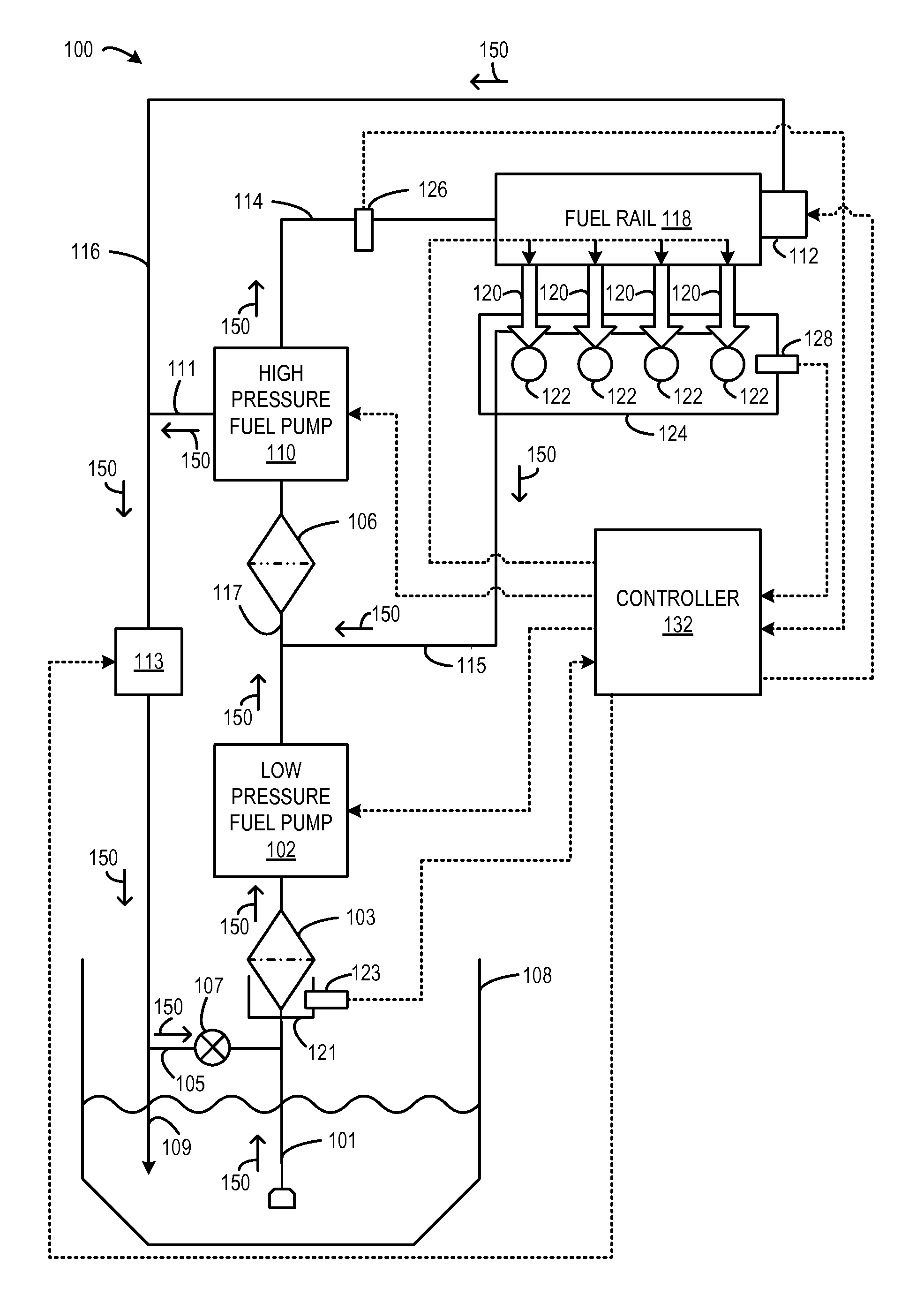
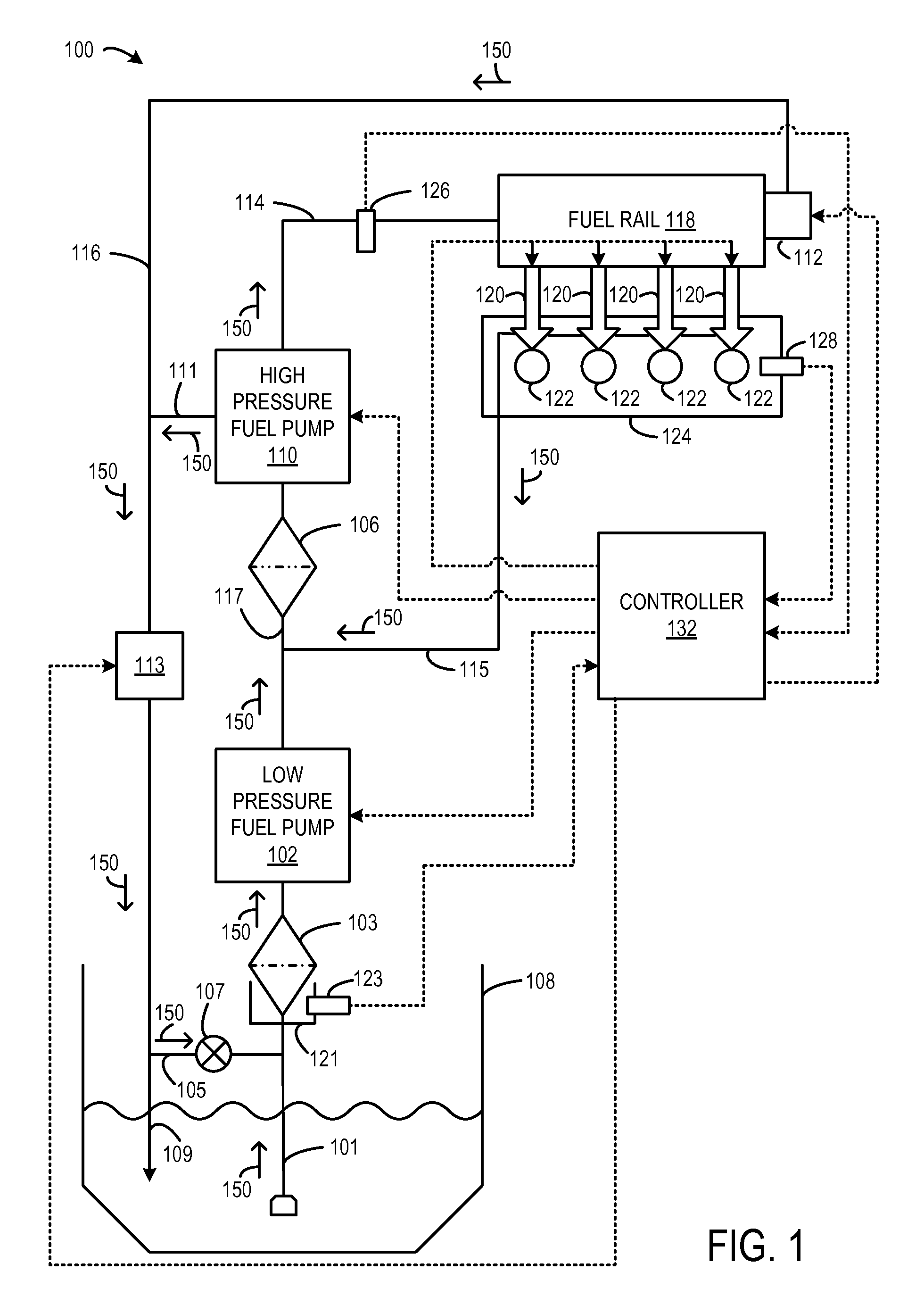
[0011]FIG. 1 shows a schematic depiction of a fuel delivery system 100 for an internal combustion engine, such as a diesel engine, for use in a vehicle. As shown, fuel may be delivered through fuel delivery system 100 through various fuel lines and through various different components in a direction as indicated generally by arrows 150.

[0012]Fuel delivery system 100 includes a low-pressure fuel pump 102 to pump liquid fuel from fuel tank 108. In this embodiment, fuel pump 102 is an electronically controlled variable speed lift pump. In some cases, low-pressure fuel pump 102 may only operate at a limited number of speeds.

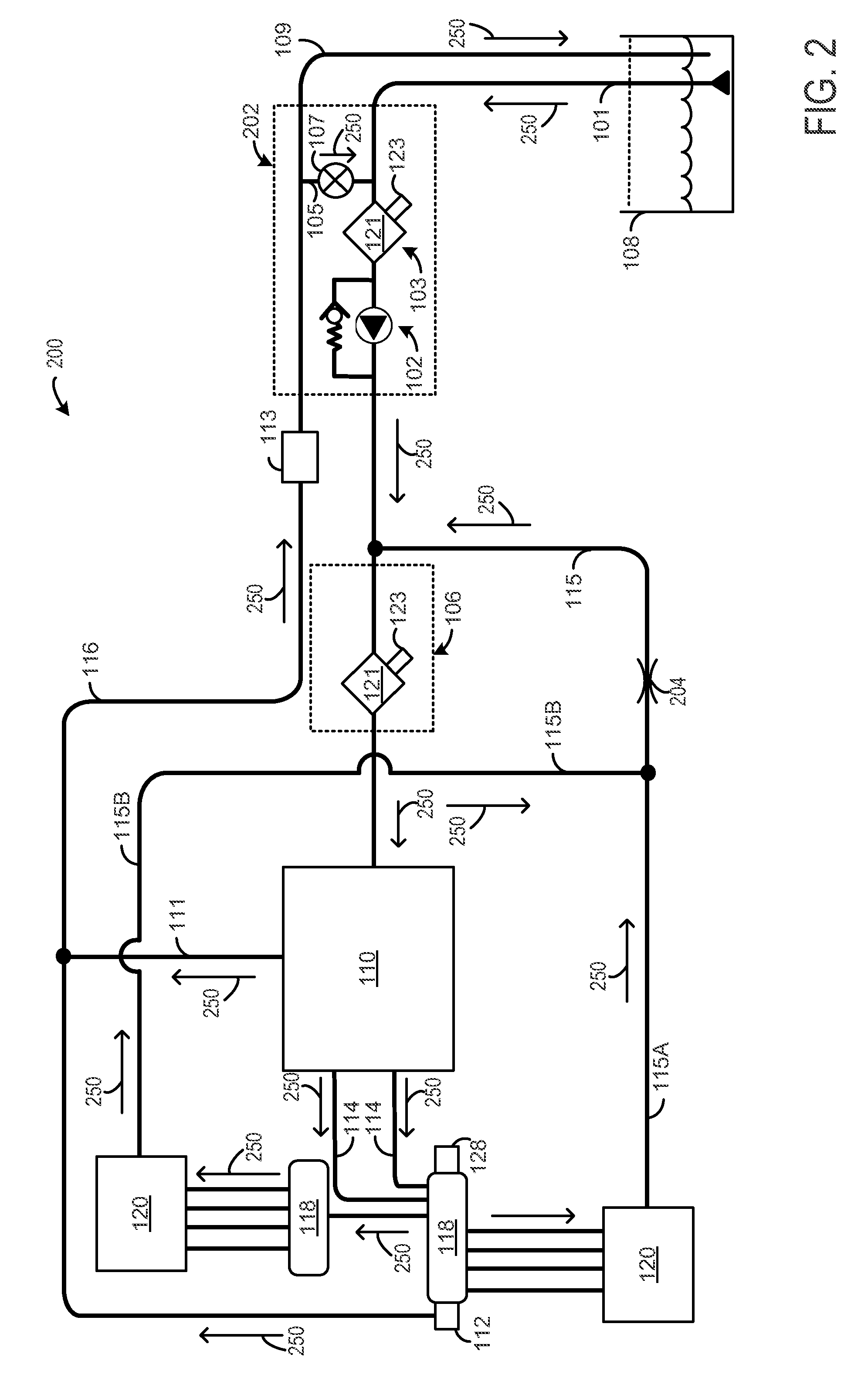
[0013]A first fuel filter 103 is disposed upstream of the low-pressure fuel pump 102 in low pressure pump intake line 101. First fuel filter 103 may remove larger impurities that may be contained in the fuel that could potentially damage vital engine components. For example, the first fuel filter may have a 10 μm filtration size. Further, as best shown in FIG. 2, the...


PUM


Abstract

A fuel system for an engine is provided herein. According to one embodiment, the fuel system includes a fuel supply coupled to a low pressure fuel pump, the low pressure fuel pump coupled to a high pressure fuel pump to provide fuel to a fuel rail. Further, the fuel system includes a plurality of injectors coupled to the fuel rail to provide fuel to a plurality of engine cylinders. Further still, the fuel system includes a first fuel return line coupling the fuel rail to the fuel supply and a thermal recirculation valve, the thermal recirculation valve further coupled to a low pressure pump intake line; a second fuel return line coupling the high pressure fuel pump to the first fuel return line; and a third fuel return line coupling the plurality of injectors to a high pressure pump intake line.

Description

CROSS REFERENCE TO RELATED APPLICATION[0001]This application claims priority to U.S. Provisional Application No. 61 / 447,533, filed Feb. 28, 2011, and titled MULTI-STAGED FUEL RETURN SYSTEM, the entirety of which is incorporated herein by reference for all purposes.BACKGROUND AND SUMMARY[0002]Many diesel engines require both a higher pressure fuel system and a lower pressure fuel system to supply fuel for engine operation and return it back to the fuel tank. The lower pressure fuel system supplies fuel to the higher pressure fuel system, at the desired pressure, temperature, quantity and quality (cleanliness and water free), which in turn pressurizes that fuel and supplies that fuel to the engine. The lower pressure fuel system has another function; it returns unused fuel from the high pressure fuel system back into the low pressure fuel system and tank. In a higher pressure fuel system, the majority of fuel is used by the engine for combustion; however, portions of the fuel are used...

Claims


Application Information

Patent Timeline
Patent Type & Authority Patents(United States)
IPC IPC(8): F02M37/22F02D41/06F02D41/38F02M63/02
CPCF02D41/3854F02D41/064F02M63/0225F02D41/3863F02D41/3845
Inventor FULTON, BRIEN LLOYDBROWN, BRAD ALLENARMESTO, CARLOSCASTLEBERRY, LARRYSZYMUSIAK, SCOTT J.
Owner FORD GLOBAL TECH LLC
Why Eureka
Try Eureka