
Converter arrangement and method for converting an analogue input signal into a digital output signal

a converter arrangement and digital output technology, applied in the field of converter arrangement and method for converting an analogue input signal into a digital output signal, can solve the problem of not having the required prior knowledge of the physical cause of the distortion generated in the signal, and achieve the effect of improving the robustness of the overall system, simplifying and speeding up the identification process

Active Publication Date: 2015-10-20
KLIPPEL WOLFGANG
View PDF14 Cites 1 Cited by
  • Summary
  • Abstract
  • Description
  • Claims
  • Application Information

AI Technical Summary

Benefits of technology

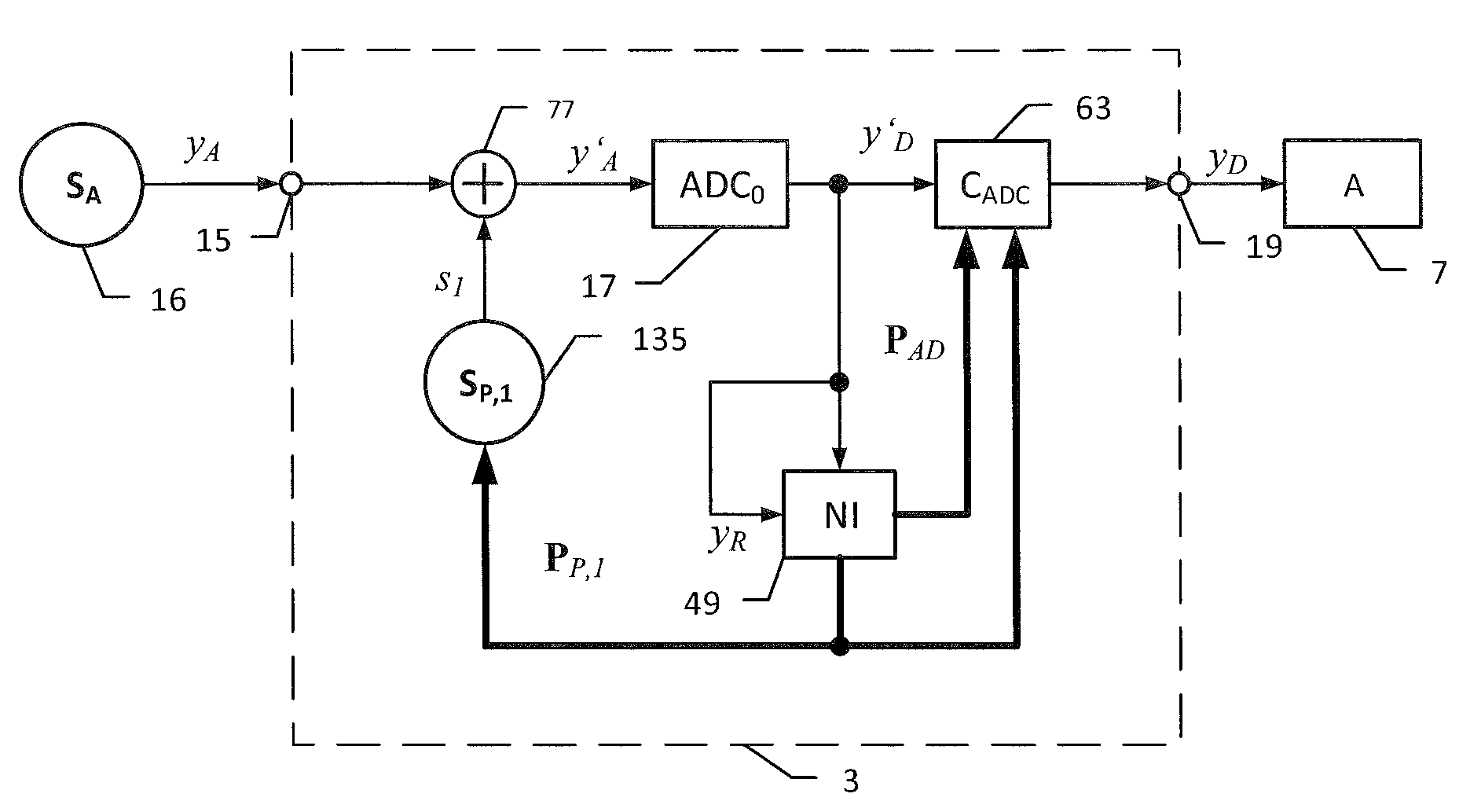
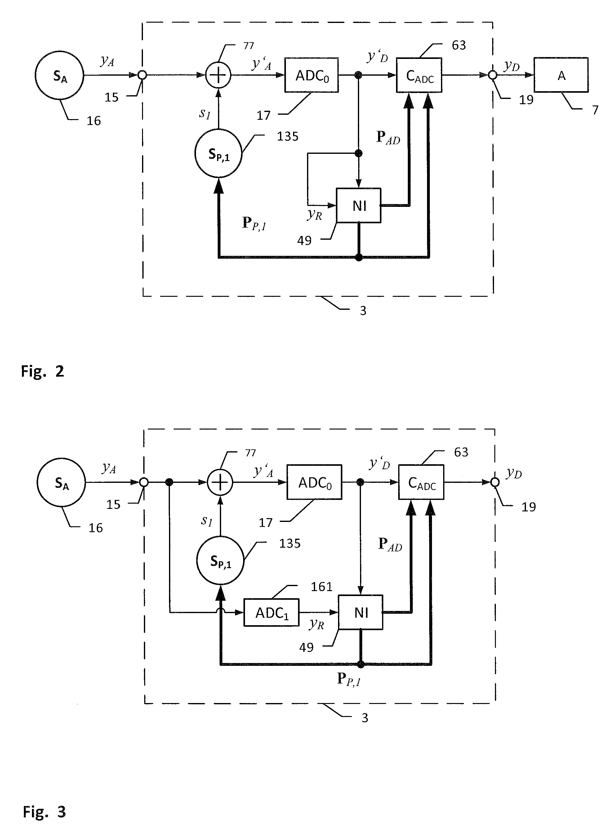
[0010]The invention uses nonlinear system identification to estimate an ADC parameter vector PAD, which provides information about a nonlinear ADC model. The ADC parameter vector PAD are largely independent of the analog input signal yA and need to be updated only if the ADC has time-variant properties changing for example by ambient temperature or other external influences. The nonlinear system identification uses the distorted ADC output signal y′D or the linearized digital output signal yD. The full identification of the nonlinear ADC model can be skipped if a test tone or a multi-tone complex is used as analog input signal yA. In this case, only selected parameters are identified, which are needed for the compensation of distortion generated by the particular stimulus. This simplifies and speeds up the identification process and improves the robustness of the overall system.

Problems solved by technology

Furthermore, there is no prior knowledge about the physical cause of the distortion generated in the signal required.

Method used


Image

  • Converter arrangement and method for converting an analogue input signal into a digital output signal
  • Converter arrangement and method for converting an analogue input signal into a digital output signal
  • Converter arrangement and method for converting an analogue input signal into a digital output signal

Examples


Embodiment Construction

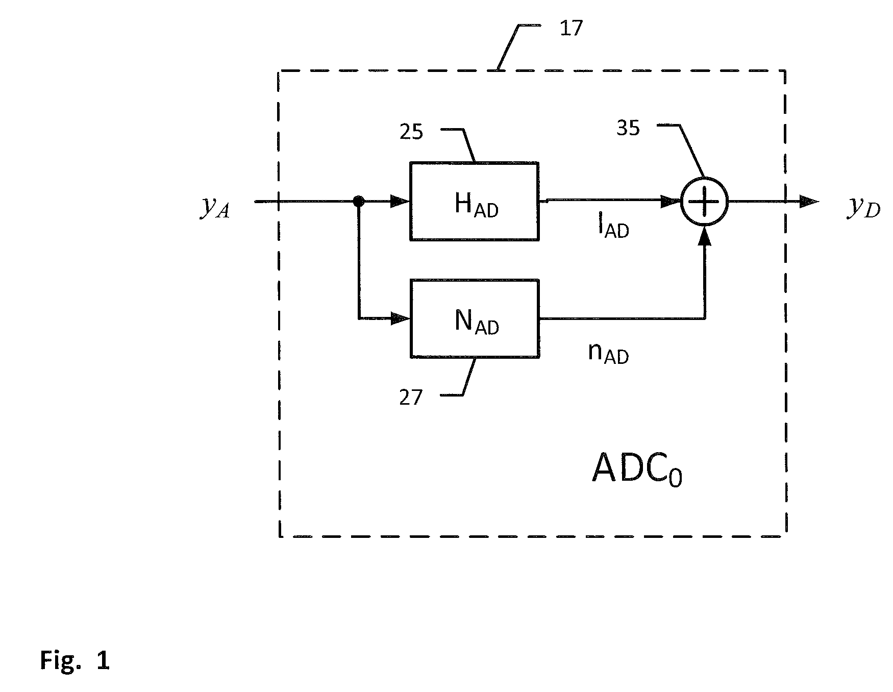
[0030]FIG. 1 shows a model of the ADC 17, that contains a linear element 25 with the transfer function HAD(s) and a nonlinear element 27, whose inputs are supplied with the analog input signal yA. Their output signals are summed up by adder 35 generating the digital output signal

yD=lAD+nAD.  (1)

The linear signal can be expressed as

lAD=L−1{HAD(s)}*yA  (2)

using the convolution operation *, the Laplace operator s and the inverse Laplace transform L−1{ }. The nonlinear distortion signal

[0031]nAD⁡(t)=∑k=2K⁢∫⁢…⁢⁢∫hADk⁡(τ1,…⁢,τk)⁢yA⁡(t-τ1)⁢⁢…⁢⁢yA⁡(t-τ1)⁢ⅆτ1⁢⁢…⁢⁢ⅆτk(3)

[0032]is expressed as a truncated Volterra series comprising kth-order homogeneous power systems with the kernel function hADk(τ1, . . . , τk).

[0033]FIG. 2 shows the arrangement for the linearization of the ADC 17 according to the invention using a generator 135, which generates a first perturbation signal s1 using digital control information PP,1. The perturbation signal s1 is incoherent to the analog input signal yA yielding...


PUM


Abstract

The invention relates to an arrangement and a method for the identification of parameters in a nonlinear model of an analog-to-digital converter (ADC 17) and the use of this information to reduce the nonlinear distortions of the ADC. A parameter estimator determines an AD parameter vector PAD which describes the nonlinearities of the ADC (17). According to the invention the ADC is excited by a perturbed input signal y′A generated by adder 77 which combines the analog input signal yA with perturbation signal s1 provided by generator. The nonlinear system identification uses intermodulation distortion generated in the digital ADC output signal y′D which are not found in the analog input signal yA. A nonlinear AD compensation element compensates based on parameter vector PAD the nonlinear distortion generated by the ADC and generates the linearized output signal yD. Digital control information PP,1 are used to generate the perturbation signal s1 in generator and to remove the perturbation signal the compensation element. The linearized ADC (is the basis for linearizing digital-analog-converters (DAC), amplifiers and other hardware components.

Description

CROSS-REFERENCE TO RELATED APPLICATIONS[0001]This application is a non-provisional application of German Application No. 10 2013 021 599.4, filed Dec. 19, 2013 in German, the contents of which are hereby incorporated by reference in their entirety.FIELD OF THE INVENTION[0002]The invention relates to a converter arrangement and a method for the identification of parameters in a nonlinear model of an analog-to-digital converter (ADC) and the use of this information to reduce the nonlinear distortions of this ADC. The linearized ADC forms the basis for the linearization of a digital-to-analog converter (DAC) and the design of linear transfer systems and measuring devices.BACKGROUND OF THE INVENTION[0003]ADC and DAC are well known. ADC and DAC are converters having a nonlinear transfer characteristic that produce harmonics, intermodulation and other nonlinear distortion components in the output signal. This nonlinear distortion can be compensated by a pre-processing of the digital input...

Claims


Application Information

Patent Timeline
Patent Type & Authority Patents(United States)
IPC IPC(8): H03M1/10H03M1/06H03M1/08H03M1/46H03M1/12H03M1/66
CPCH03M1/0626H03M1/0612H03M1/089H03M1/1038H03M1/46H03M1/12H03M1/66
Inventor KLIPPEL, WOLFGANG
Owner KLIPPEL WOLFGANG
Learn More