Illumination aperture diaphragm

a technology of aperture diaphragm and aperture diaphragm, which is applied in the direction of optical radiation measurement, fluorescence/phosphorescence, nuclear engineering, etc., can solve the problems of buried fluorescence image, and difficult to accurately observe the portion emitting fluorescent light in the subject image, so as to prevent the fluorescence image and improve the light ratio

Active Publication Date: 2015-11-03
VS TECH CORP
View PDF16 Cites 7 Cited by
  • Summary
  • Abstract
  • Description
  • Claims
  • Application Information

AI Technical Summary

Benefits of technology

[0020]According to the first and second illumination aperture diaphragms of the present invention, there is formed an aperture region inside a filter region which transmits light in the wavelength region of excitation light for allowing a portion of a subject being observed to emit fluorescent light and which reduces or blocks the transmission of light in a visible light region for forming a subject image. Thus, only the light in the visible light region for forming the subject image is reduced without reducing the light in the wavelength region of the excitation light which passes through the filter region and the aperture region. Thus, when the aperture diaphragm is used in a light source device, it is possible, in a simple system configuration using a white light source, to improve the ratio between the quantity of light of the fluorescence image and the quantity of light of the subject image and prevent the fluorescence image from being buried in the subject image.
[0021]Furthermore, according to the second illumination aperture diaphragm of the present invention, the area of the aperture region is variable. Thus, when this aperture diaphragm is used in a light source device, it is possible, in a simple system configuration, to balance the quantities of light of the fluorescence image and the subject image in a more appropriate manner.

Problems solved by technology

The fluorescent light emitted from the light-sensitive substance is very weak when compared with the illumination light, thus raising the problem that the fluorescence image is buried in the subject image formed by the illumination light.
However, this method also has the problem that the fluorescence image is buried in the subject image.
However, in this method, since not only the fluorescent light in the infrared region but also the R component light forming the subject image are emphasized at the same time, it is difficult to accurately observe the portion emitting the fluorescent light in the subject image.
There is also a problem that a filter for separating the subject image into the RGB components and a mechanism for driving the same are required, leading to an increase in the complexity of the whole system configuration.
However, it is difficult to obtain an optical filter which has well-balanced transmittances for the infrared band and the visible light band when the light in the infrared band for forming the fluorescence image is very weak relative to the light in the visible light band for forming the subject image.
However, it is impossible for this light source device to balance the quantity of light between the fluorescence image and the subject image in the visible light band.
However, the band limiting rotary filter cannot change the ratio of the quantity of light between the excitation light for forming the fluorescent subject image and the light in the visible light band for forming the subject image.
Furthermore, to simultaneously observe the fluorescence image and the subject image, the band limiting rotary filter of the light source device and the RGB filter of the light-receiving device have to be synchronized with each other, thus leading to the problem of the increased complexity of the whole system configuration.
However, this case will also lead to an increase in the complexity of the whole system configuration.

Method used


Image

  • Illumination aperture diaphragm
  • Illumination aperture diaphragm
  • Illumination aperture diaphragm

Examples


Embodiment Construction

[0036]Now, the present invention will be described in more detail below with reference to the drawings. Note that the same reference characters refer to the same or equivalent elements in all the drawings.

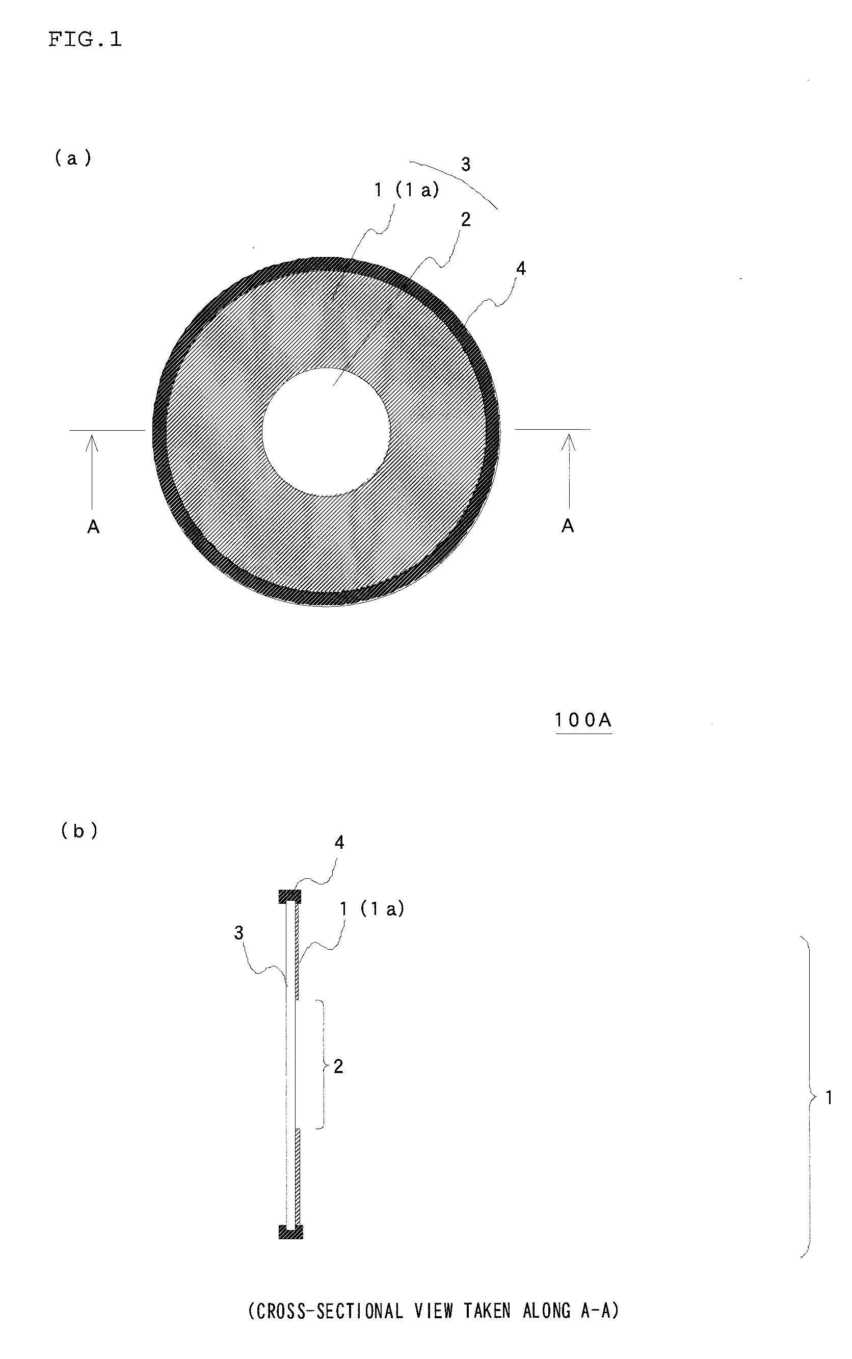
[0037]FIG. 1 includes a plan view (FIG. 1(a)) and a cross-sectional view (FIG. 1(b)) taken along A-A illustrating a doughnut-shaped aperture diaphragm 100A which is an embodiment of a first illumination aperture diaphragm according to the present invention. The doughnut-shaped aperture diaphragm 100A is made up of a flat plate-like base material 3, which has an annular filter region 1 and a circular aperture region 2 formed inside the filter region 1, and an outer frame 4 fitted over the outer periphery of the flat plate-like base material 3. More specifically, the filter region 1 has a filter layer 1a which is annularly provided on a surface of the circular, transparent, flat, plate-like base material 3, and the center region of the flat plate-like base material 3 on which no filt...


PUM

PropertyMeasurementUnit
wavelengthaaaaaaaaaa

Abstract

An illumination aperture diaphragm 100A for a light source device for supplying illumination light in an endoscopic device to simultaneously observe a subject image formed by reflected illumination light in the visible light region and a fluorescence image from a fluorescent substance in a subject has a filter region 1 formed in a flat plate-like base material 3 and an aperture region 2 formed inside the filter region 1. The filter region 1 transmits light in the wavelength region of excitation light for allowing the subject to emit fluorescent light and reduces or blocks the transmission of the light in the visible light region that forms the subject image. An illumination aperture diaphragm 200A may include a plurality of diaphragm blade members 20A.

Description

RELATED APPLICATIONS[0001]This application is a U.S. national phase application of International Application No. PCT / JP2011 / 079901 filed Dec. 22, 2011 claiming priority of Japanese Patent Application No. 2011-010056 filed Jan. 20, 2011.FIELD OF INVENTION[0002]The present invention relates to an illumination aperture diaphragm for simultaneously irradiating a subject with illumination light for observing a visible subject image and excitation light for observing a fluorescent subject image in an appropriate ratio of quantity of light.BACKGROUND ART[0003]In a medical field, there have been available a photodynamic diagnosis (PDD) and a photodynamic therapy (PDT). The PDD is a diagnosis by making use of the property of a light-sensitive substance that is distinctively accumulated in tumor bearing tissue and emits fluorescent light when being irradiated with excitation light. In the diagnosis, the light-sensitive substance is given in advance to a living body, and then the tumor bearing...

Claims


Application Information

Patent Timeline
Patent Type & Authority Patents(United States)
IPC IPC(8): A61B1/06G01N21/64A61B1/04G02B5/00G02B23/24G03B15/14G03B9/02F21V13/02F21V9/08
CPCF21V13/02A61B1/043A61B1/0638A61B1/0646A61B1/0669F21V9/08G01N21/64G02B5/005G02B23/2461G03B9/02G03B15/14A61B1/06A61N5/06G02B21/00
Inventor YAMANO, SHIROSATO, TAKAYUKI
Owner VS TECH CORP
Why Eureka
Try Eureka