
System and method for controlling delivery of ablation energy to tissue

a technology of ablation catheter and ablation catheter, which is applied in the field of system and method for controlling the delivery of ablation energy by ablation catheter to tissue, can solve the problems of insufficient ablation energy reduction, high risk of ablation therapy, so as to reduce the incidence of thrombosis, improve the control of ablation energy delivery, and minimize the effect of energy delivery

Active Publication Date: 2015-11-10
ST JUDE MEDICAL ATRIAL FIBRILLATION DIV
View PDF30 Cites 111 Cited by
  • Summary
  • Abstract
  • Description
  • Claims
  • Application Information

AI Technical Summary

Benefits of technology

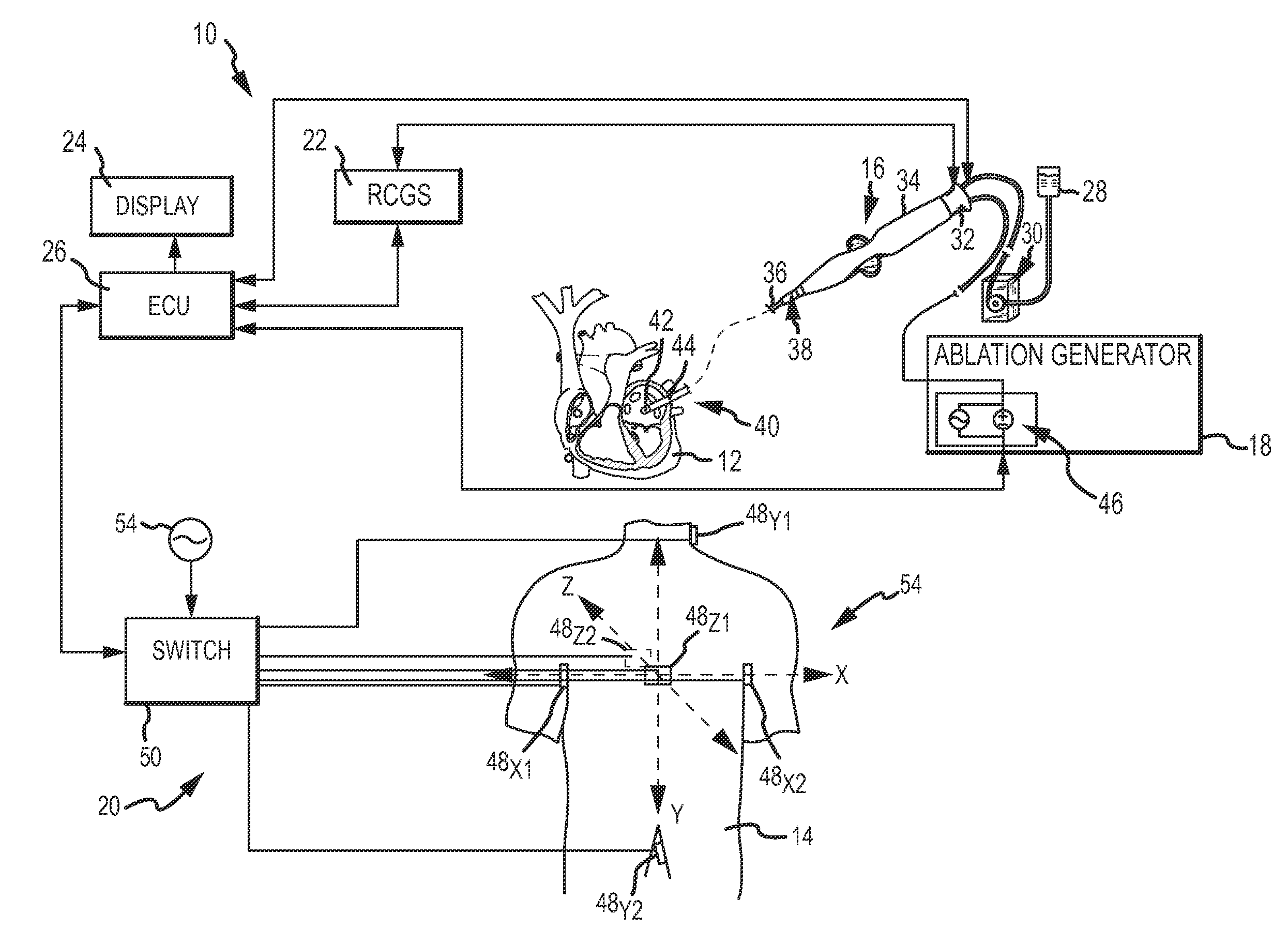
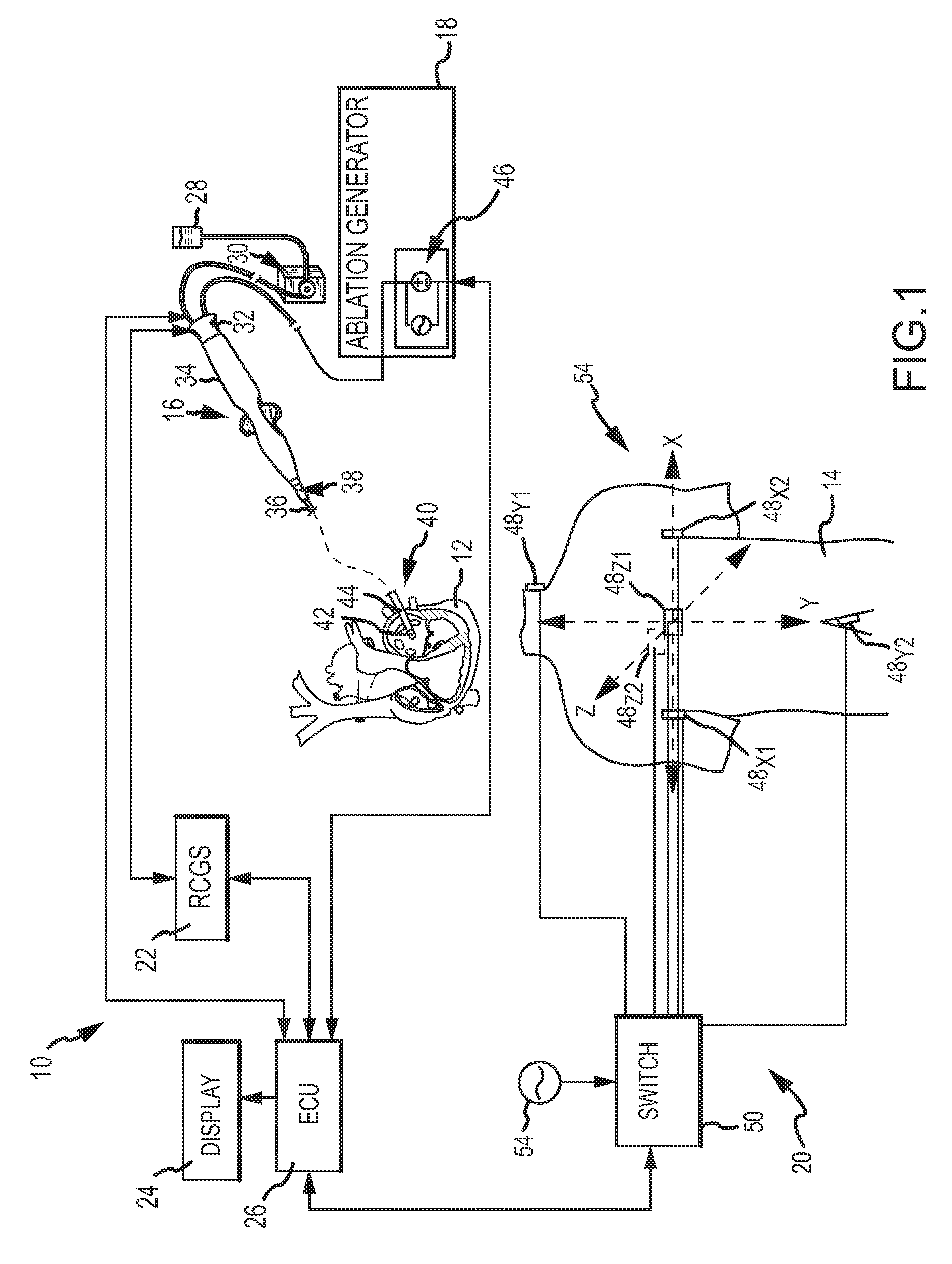
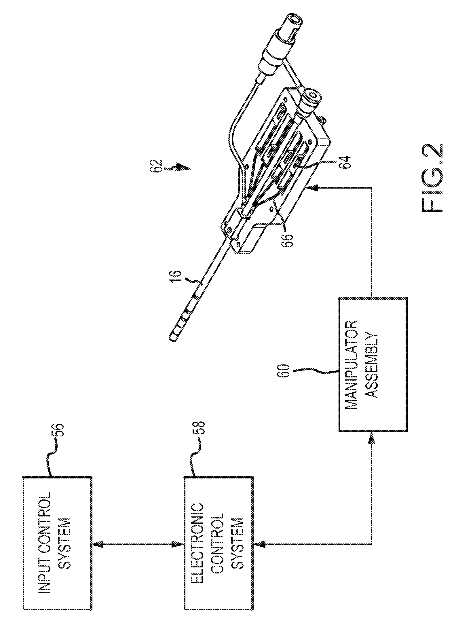
This patent describes a system and method for controlling the delivery of ablation energy to tissue in the body. The system and method improve control to minimize energy delivery into the blood and reduce the risk of thrombus formation during a procedure. This allows for finer control of ablation energy delivery to tissue based on changes in characteristics associated with the delivery.

Problems solved by technology

Arrhythmia can create a variety of dangerous conditions including irregular heart rates, loss of synchronous atrioventricular contractions and stasis of blood flow which can lead to a variety of ailments and even death.
There are, however, a number of risks associated with ablation therapy.
If the thrombus becomes dislodged, there is a risk that the thrombus will travel to a location where the thrombus will prevent further bloodflow and result in stroke.
Many catheters employ saline irrigation to cool the tip of the catheter, but irrigation may fail to sufficiently reduce heat and thrombus formation.
Thrombii may also be removed by employing vacuum force through the sheath in which the catheter is disposed or by removing the catheter itself, but both of these actions may result in dislodgement of the thrombus.

Method used


Image

  • System and method for controlling delivery of ablation energy to tissue
  • System and method for controlling delivery of ablation energy to tissue
  • System and method for controlling delivery of ablation energy to tissue

Examples


Embodiment Construction

[0018]Various embodiments are described herein of various apparatuses, systems, and / or methods. Numerous specific details are set forth to provide a thorough understanding of the overall structure, function, manufacture, and use of the embodiments as described in the specification and illustrated in the accompanying drawings. It will be understood by those skilled in the art, however, that the embodiments may be practiced without such specific details. In other instances, well-known operations, components, and elements have not been described in detail so as not to obscure the embodiments described in the specification. Those of ordinary skill in the art will understand that the embodiments described and illustrated herein are non-limiting examples, and thus it can be appreciated that the specific structural and functional details disclosed herein may be representative and do not necessarily limit the scope of the embodiments, the scope of which is defined solely by the appended cla...


PUM


Abstract

A system for controlling delivery of ablation energy by an ablation catheter to tissue in a body is provided. The system includes an electronic control unit configured to determine, responsive to a measurement signal from the ablation catheter, a value for a characteristic associated with the delivery of ablation energy to the tissue. In one embodiment, the characteristic is the degree of contact between the ablation catheter and the tissue. The unit is further configured to generate a control signal, responsive to the determined value of the characteristic, to control an amount of energy delivered from an ablation delivery element on the ablation catheter to the tissue. The amount of energy varies in response to the determined value of the characteristic when the determined value of the characteristic meets a predetermined condition relative to a threshold value for the characteristic.

Description

CROSS-REFERENCE TO RELATED APPLICATIONS[0001]This application claims priority to U.S. Provisional Patent Application No. 61 / 642,979 filed May 4, 2012, the entire disclosure of which is incorporated herein by reference.BACKGROUND OF THE INVENTION[0002]a. Field of the Invention[0003]This invention relates to a system and method for controlling delivery of ablation energy by an ablation catheter to tissue in a body. In particular, the instant invention relates to a system and method that enable fine control or titration of the delivery of ablation energy to tissue in response to changes in various characteristics associated with the delivery of ablation energy to the tissue such as the degree of contact between the ablation catheter and tissue.[0004]b. Background Art[0005]It is well known to use ablation catheters to create tissue necrosis in cardiac tissue to correct cardiac arrhythmias (including, but not limited to, atrial fibrillation, atrial flutter, atrial tachycardia and ventric...

Claims


Application Information

Patent Timeline
Patent Type & Authority Patents(United States)
IPC IPC(8): A61B18/18A61B18/14A61B19/00A61B18/00
CPCA61B18/1492A61B2018/00577A61B2018/00666A61B2018/00702A61B2018/00791A61B2018/00839A61B2018/00875A61B2019/465A61B2090/065
Inventor OLSON, ERIC STEVEN
Owner ST JUDE MEDICAL ATRIAL FIBRILLATION DIV
Learn More