Burner for a thermal post-combustion device

Inactive Publication Date: 2015-11-24
EISENMANN AG
View PDF23 Cites 2 Cited by
  • Summary
  • Abstract
  • Description
  • Claims
  • Application Information

AI Technical Summary

Benefits of technology

[0009]An object of the present invention is to design a burner of the type mentioned at the outset such that particularly

Problems solved by technology

For a given volume, it has a comparatively small surface and, according to general opinion, is therefore not actually suitable for achieving good combustion values.

Method used


Image

  • Burner for a thermal post-combustion device
  • Burner for a thermal post-combustion device
  • Burner for a thermal post-combustion device

Examples


Embodiment Construction

[0025]While this invention is susceptible of embodiment in many different forms, there is shown in the drawings and will herein be described in detail one or more embodiments with the understanding that the present disclosure is to be considered as an exemplification of the principles of the invention and is not intended to limit the invention to the embodiments illustrated.

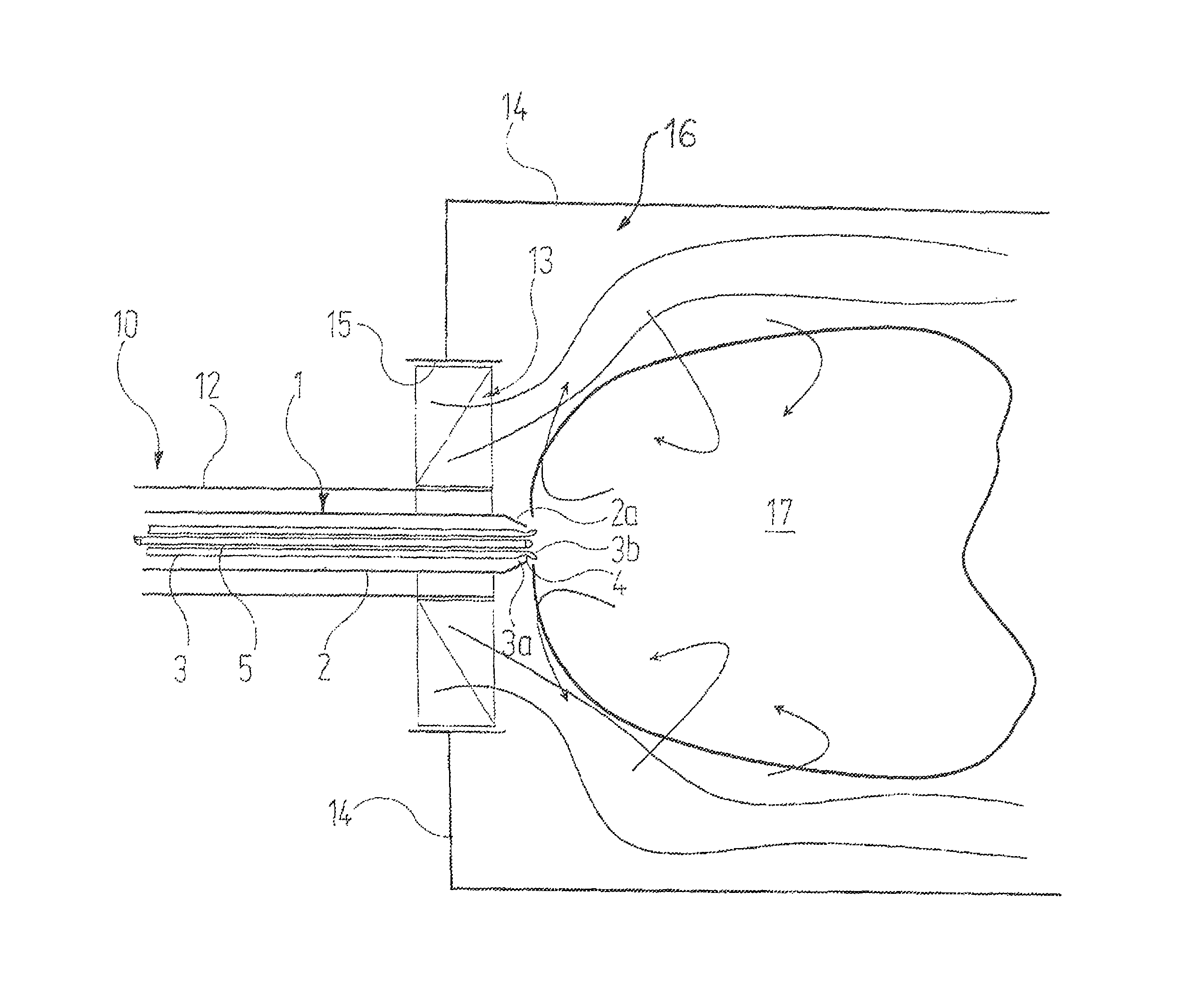
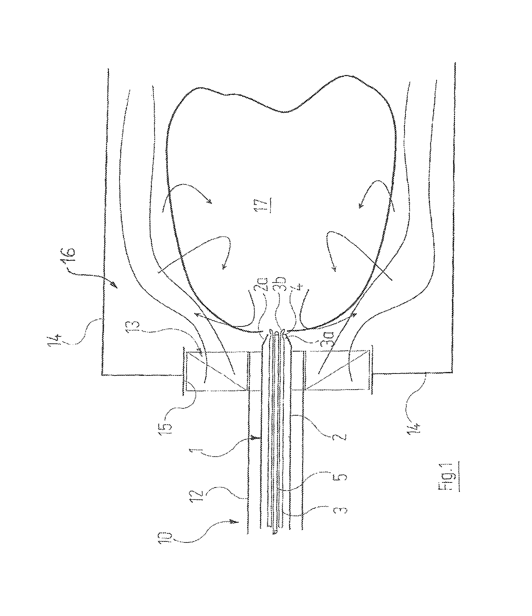
[0026]Reference is made first to FIG. 1. Represented therein is that region of a burner, denoted as a whole by the reference 10, that is disposed within the insulated outer housing of a thermal post-combustion device. On account of the “environment” in which this burner 10 is used, reference is made to DE 102 37 604 B4, already mentioned above. Unless otherwise stated in the following, the statements made therein concerning the connection, design and manner of operation of the burner 10 apply here in like manner. In particular, it also applies in this case that the burner 10 is introduced as a whole, with its fre...


PUM


Abstract

The invention describes a burner for a thermal post-combustion device, which has a burner jet arranged in a housing. Arranged on the end region of the housing is a swirl apparatus, through which the exhaust gas to be purified can be made to flow. The burner jet comprises an outer tube and an inner tube, wherein it is possible for combustion gas to be made to flow through the interspace between said two tubes as far as an annular outlet gap in the end region thereof. The flow path for the combustion gas has a bottleneck in the vicinity of the outlet gap. In this way, a compact flame can be achieved, the form of which can be designated “bell-shaped” and which, for a given volume, has a relatively small surface. Although, such a flame has poor CO2 values, the swirl apparatus ensures that the exhaust gas burns in the flame with very low NOx and CO values.

Description

RELATED APPLICATIONS[0001]This application claims the filing benefit of International Patent Application No. PCT / EP2010 / 001113, filed Feb. 23, 2010, which claims the filing benefit of German Patent Application No. 10 2009 010 274.4 filed Feb. 24, 2009, the contents of which are incorporated herein by reference.TECHNICAL FIELD[0002]The invention relates to a burner for a thermal post-combustion device, comprising[0003]a) a housing;[0004]b) a combustion nozzle, which is disposed in the housing and has a tube through which combustion gas can flow and that has at last one outlet opening for the combustion gas;[0005]c) an eddy apparatus, which is attached to an end region of the housing and through which the exhaust gas to be purified can flow.BACKGROUND OF THE INVENTION[0006]Thermal post-combustion devices are intended to combust as completely as possible and with maximum efficiency, i.e. with a minimum burner power, the impurities entrained in the exhaust air requiring disposal. From t...

Claims


Application Information

Patent Timeline
IPC IPC(8): F23B10/02F23D14/24F23G7/06F23D14/58F23D14/48
CPCF23D14/24F23D14/48F23D14/58F23G7/06F23D2900/14481
Inventor GMINDER, CHRISTOFKATEFIDIS, APOSTOLOS
Owner EISENMANN AG
Why Eureka
Try Eureka