Cell sorter system and method

a cell sorter and cell sorting technology, applied in the field of flow cytometers and instruments, can solve the problems of compromising the quality of the fraction or rendering it unfit for therapeutic administration, confined flow sorting, and loss of valuable particles which are often presen

Active Publication Date: 2015-12-01
BECTON DICKINSON & CO
View PDF40 Cites 62 Cited by
  • Summary
  • Abstract
  • Description
  • Claims
  • Application Information

AI Technical Summary

Benefits of technology

[0005]A common flow sorting technique utilizes drop sorting in which a fluid stream containing linearly segregated particles is broken into drops and the drops containing particles of interest are electrically charged and deflected into a collection tube by passage through an electric field. Current drop sorting systems are capable of forming drops at a rate of 100,000 drops / second in a fluid stream that is passed through a nozzle having a diameter less than 100 micrometers. Drop sorting requires that the drops break off from the stream at a fixed distance from the nozzle tip. The distance is normally on the order of a few millimeters from the nozzle tip and can be maintained for an unperturbed fluid stream by oscillating the nozzle tip at a predefined frequency.
[0008]Although diagnostic flow cytometers have been made available for common use in a variety of settings, flow sorting is more complicated and has been confined primarily to core facilities having dedicated operators. Currently flow sorters require relatively complicated setup and alignment procedures that often necessitate highly trained operators. While flow analyzers have seen many improvements towards ease of use due to automation and simplification, most of the improvements in flow sorters have been directed to increasing sort speed and the number of parameters used. The increases in speed and number of parameters have had the effect of increasing the complexity and precision required in flow sorters.
[0010]Provided herein are improved cell sorter systems and methods. Such systems and methods provide a self-stabilizing sorter jet to automate calibration and address the issue of drift in cell sorting systems. The systems and methods presented make it possible to determine and set the charge delay interval (CDI) automatically with circuitry in the cell sorter. These circuits can set, monitor, and adjust the time delay continuously, allowing for a completely automatic, autonomous, turn-key, self-stabilizing sorter jet.
[0011]Presented herein are also systems and methods for automatically determining the phase of the break off point of the jet (PBP), making it possible to know when the drop with the cell separates from the jet. By combining the presented systems and methods with methods for automatically determining the phase of the drop drive signal when an event (e.g., cell) passes the intersection point of the laser and the jet of a cell sorter (as described in U.S. Pat. No. 7,679,039, which is herein incorporated by reference in its entirety), the distance between measurement point (e.g., at the LJI) and the jet break-off point (BOP) can be set and maintained at a whole number (n) of drops.

Problems solved by technology

Perturbations in a fluid stream, including turbulence caused by variability in the size of particles present in typical biological samples or drift in cytometer components can significantly impact the ability to predict which drop will contain a particle of interest Improper prediction of which drop contains a particle can lead to loss of valuable particles which are often present in small amounts in biological samples.
Even a brief lapse in the ability to accurately predict the contents of a drop can contaminate a fraction of desired particles with unwanted particles, thereby compromising the quality of the fraction or rendering it unfit for therapeutic administration.
Although diagnostic flow cytometers have been made available for common use in a variety of settings, flow sorting is more complicated and has been confined primarily to core facilities having dedicated operators.
Currently flow sorters require relatively complicated setup and alignment procedures that often necessitate highly trained operators.
The increases in speed and number of parameters have had the effect of increasing the complexity and precision required in flow sorters.
In addition, because the time delay is adjusted before the sort it is prone to drift due to pressure and temperature changes that occur over the duration of the sort.

Method used


Image

  • Cell sorter system and method
  • Cell sorter system and method
  • Cell sorter system and method

Examples


Embodiment Construction

[0021]The following detailed description of the figures refers to the accompanying drawings that illustrate an exemplary embodiment of a cell sorter system. Other embodiments are possible. Modifications may be made to the embodiment described herein without departing from the spirit and scope of the present invention. Therefore, the following detailed description is not meant to be limiting.

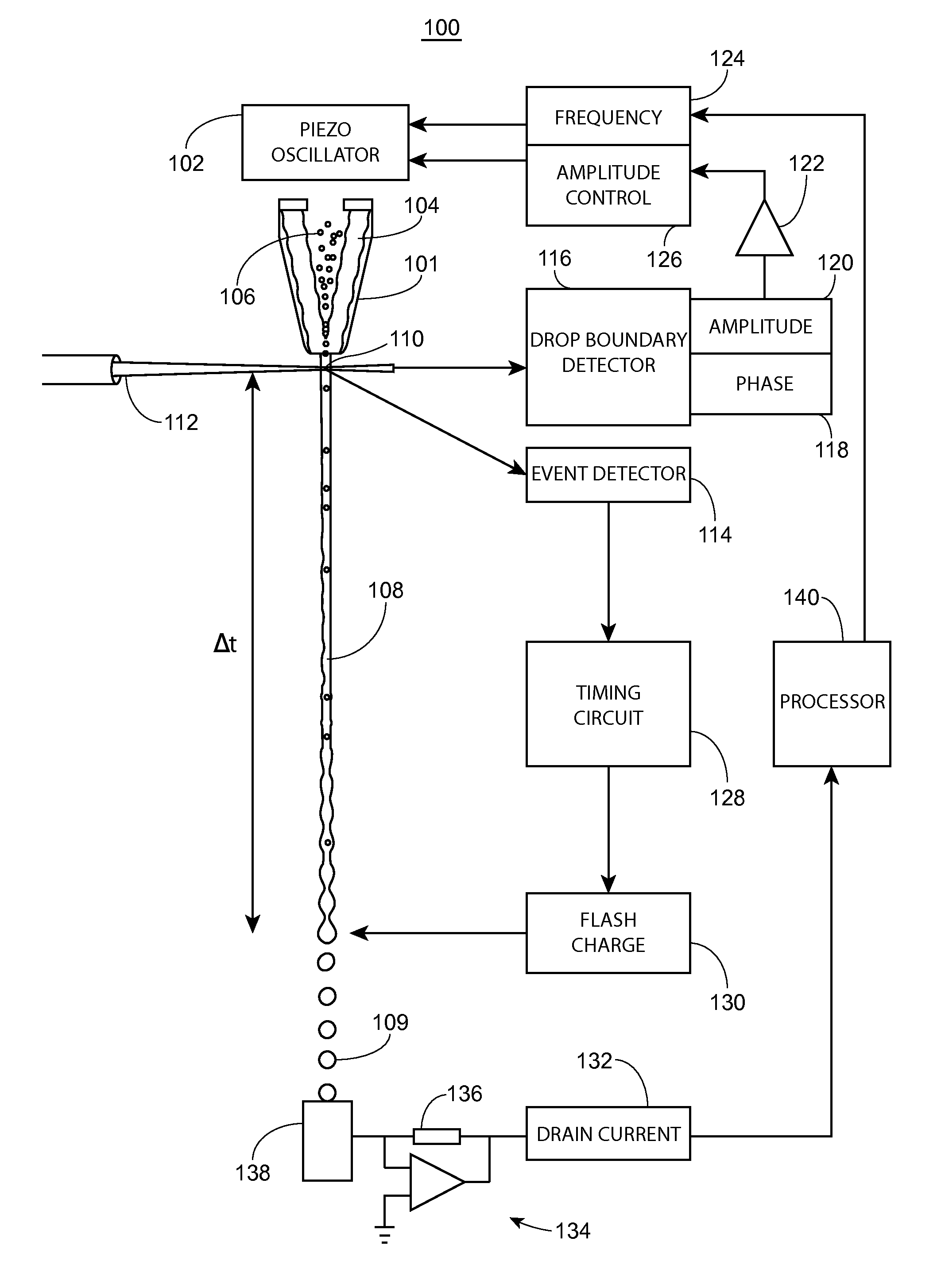
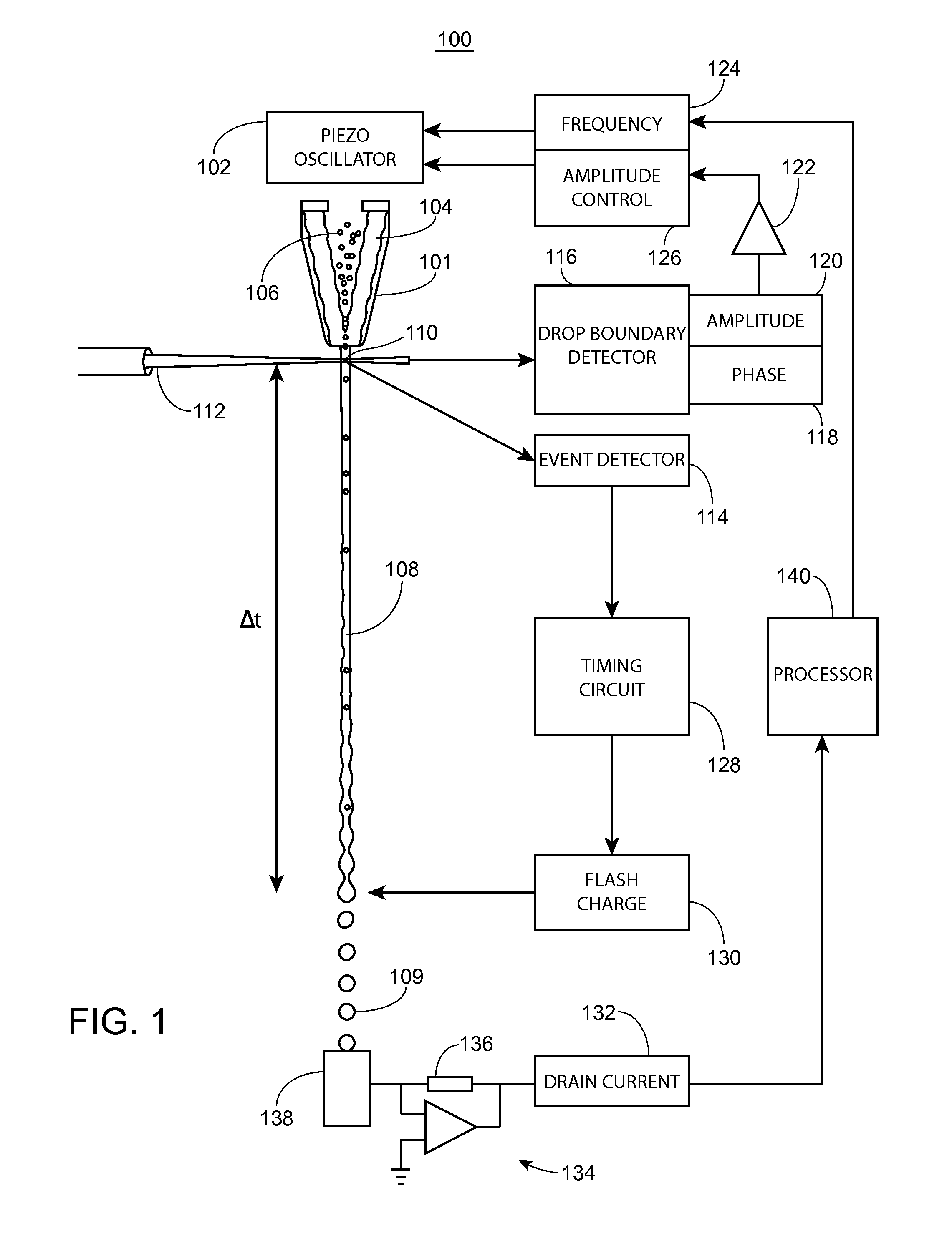
[0022]FIG. 1 is a schematic drawing of a cell sorter system 100, in accordance with one embodiment presented herein. As shown in FIG. 1, a drop formation transducer (e.g., piezo-oscillator) 102 is coupled to a fluid conduit, such as nozzle 101. Within nozzle 101, sheath fluid 104 hydrodynamically focuses a sample fluid 106 into a stream 108. Within stream 108, particles (e.g., cells) are lined up in single file to cross a laser-stream intersect 110 (e.g., the LJI), irradiated by an irradiation source (e.g., laser) 112. Vibration of piezo-oscillator 102 causes stream 108 to break into a plurality ...


PUM

PropertyMeasurementUnit
diameteraaaaaaaaaa
chargeaaaaaaaaaa
currentaaaaaaaaaa

Abstract

Provided herein are improved cell sorter systems and methods. Such systems and methods provide a self-stabilizing sorter jet to automate calibration, and address the issue of drift in cell sorting systems. The systems and methods presented make it possible to determine and set the charge delay interval automatically with circuitry in the cell sorter. These circuits can set, monitor, and adjust the time delay continuously, allowing for a completely automatic, autonomous, turn-key, self-stabilizing sorter jet.

Description

CROSS-REFERENCE TO RELATED APPLICATIONS[0001]Pursuant to 35 U.S.C. §119 (e) this application claims priority to the filing date of U.S. Provisional Patent Application Ser. No. 61 / 480,872 filed Apr. 29, 2011; the disclosure of which application is herein incorporated by reference.INTRODUCTION[0002]The present invention relates to flow cytometers and instruments for high speed identification and sorting of particles, such as cells.[0003]Flow cytometry is a valuable method for the analysis and isolation of biological particles such as cells and constituent molecules. As such it has a wide range of diagnostic and therapeutic applications. The method utilizes a fluid stream to linearly segregate particles such that they can pass, single file, through a detection apparatus. Individual cells can be distinguished according to their location in the fluid stream and the presence of detectable markers. Thus, a flow cytometer can be used to produce a diagnostic profile of a population of biolog...

Claims


Application Information

Patent Timeline
Patent Type & Authority Patents(United States)
IPC IPC(8): G01N15/14C12N13/00C12M1/00C12Q3/00G01N15/10B01L3/00
CPCC12Q3/00C12M47/04C12N13/00G01N2015/1081G01N15/1031G01N15/14B01L3/502715G01N15/1012G01N2015/0065G01N2015/1006G01N2015/149
Inventor VAN DEN ENGH, GER
Owner BECTON DICKINSON & CO
Why Eureka
Try Eureka