High thermal conductivity shell molds

a shell mold and high thermal conductivity technology, applied in the field of shell mold compositions, can solve the problems of limited directional solidification of heat extraction from solidifying casting in liquid metal cooling (lmc), and achieve the effect of high thermal conductivity and high thermal conductivity

Active Publication Date: 2015-12-08
GENERAL ELECTRIC CO
View PDF17 Cites 0 Cited by
  • Summary
  • Abstract
  • Description
  • Claims
  • Application Information

AI Technical Summary

Problems solved by technology

Heat extraction from solidifying casting in Liquid Metal Cooling (LMC) directional solidification is limited by shell heat conduction when the conventional shell molds are applied.

Method used


Image

  • High thermal conductivity shell molds
  • High thermal conductivity shell molds
  • High thermal conductivity shell molds

Examples


example

[0032]The following example is presented for illustrative purposes only, and is not intended to limit the scope of the invention.

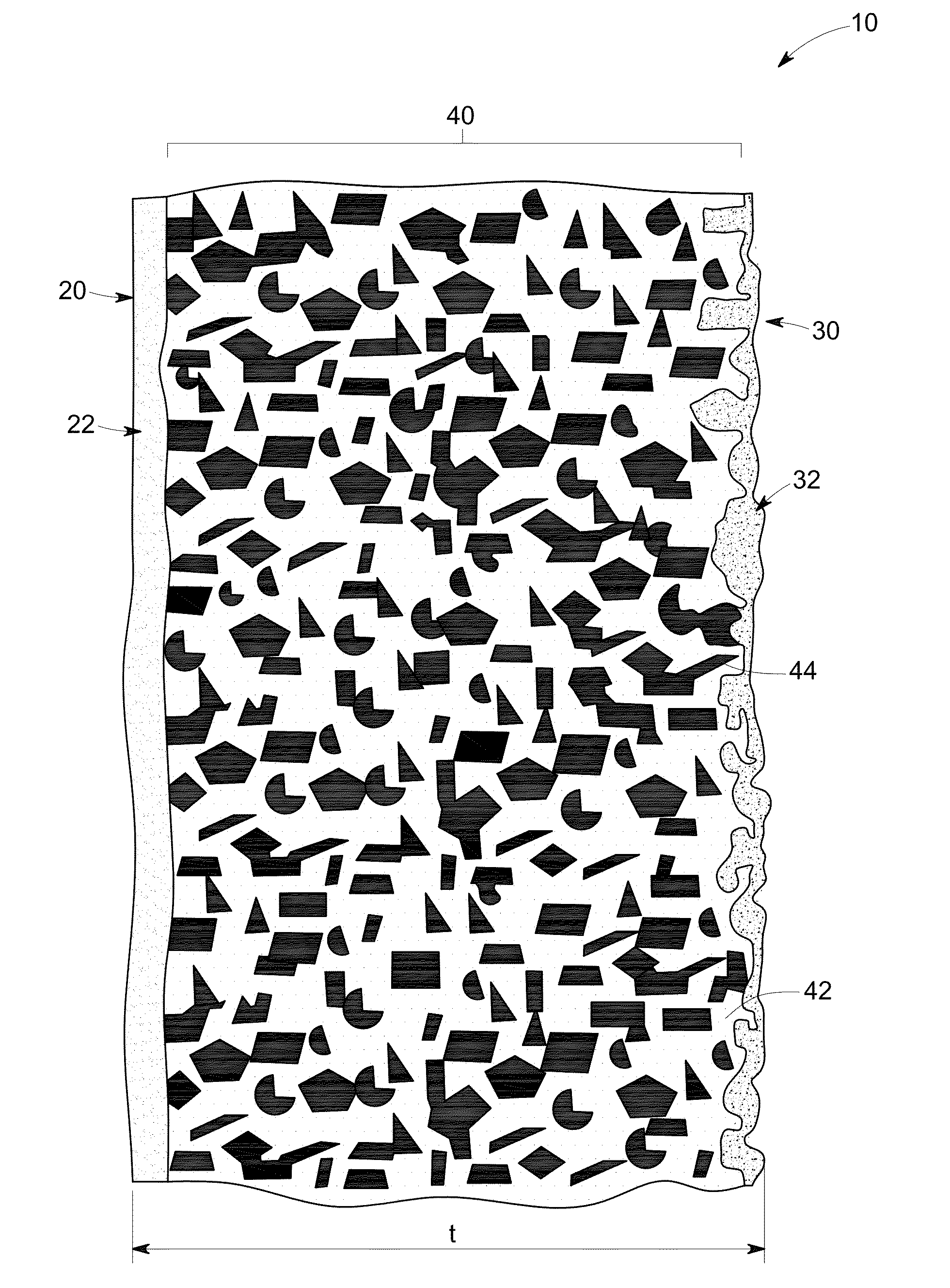
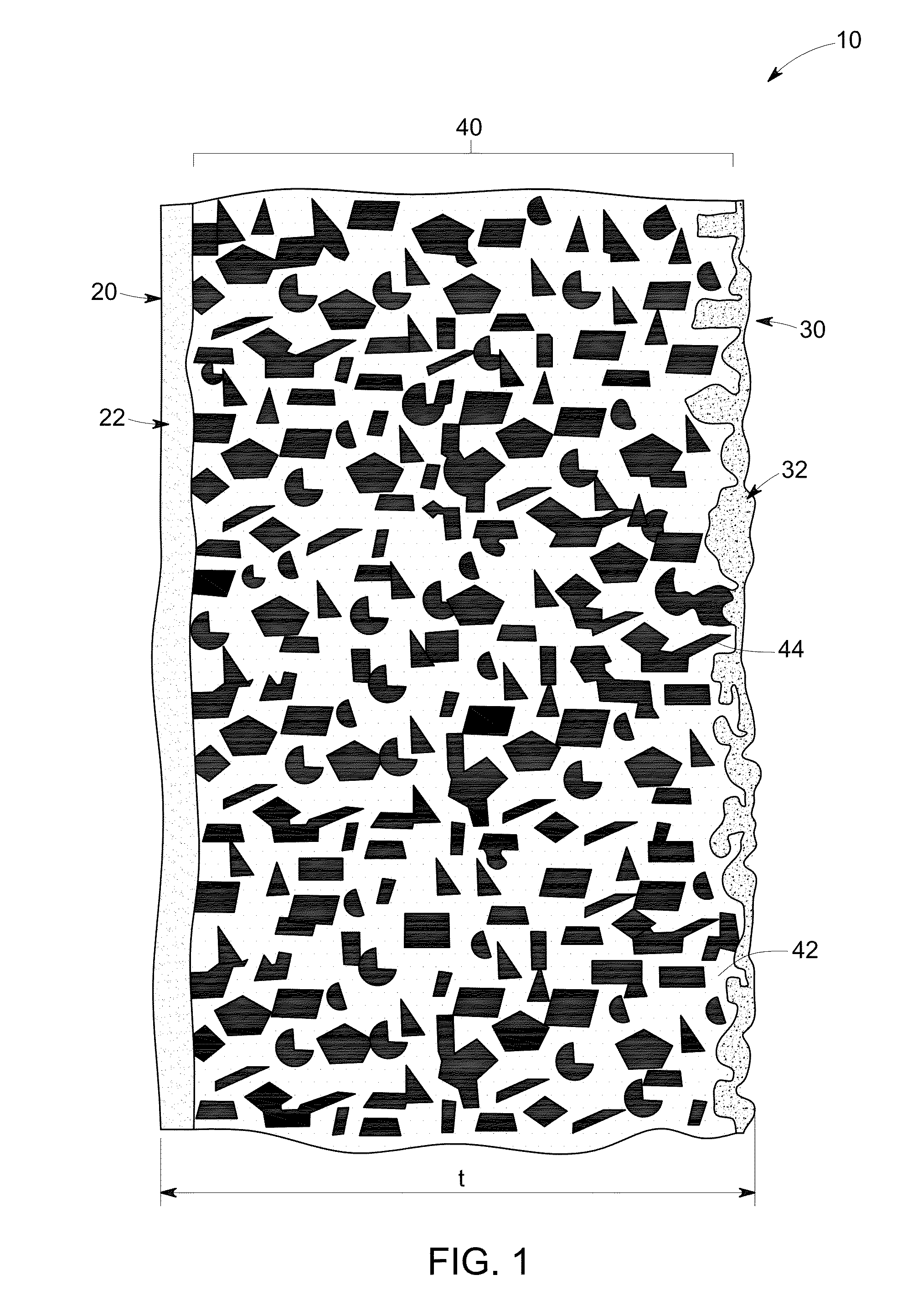
[0033]High thermal conductivity of the shell mold 10 is a desirable property in many casting applications. For example, higher heat extraction rate in an alloy (ALNICO) casting having about 8-12 atomic % Al, about 15-26 atomic % Ni, about 5-24 atomic % Co, up to about 6 atomic % Cu, up to about 1 atomic % Ti, with the balance Fe, was shown to have a significant effect on the demagnetizing properties of the ALNICO alloys formed as can be seen from the following example.

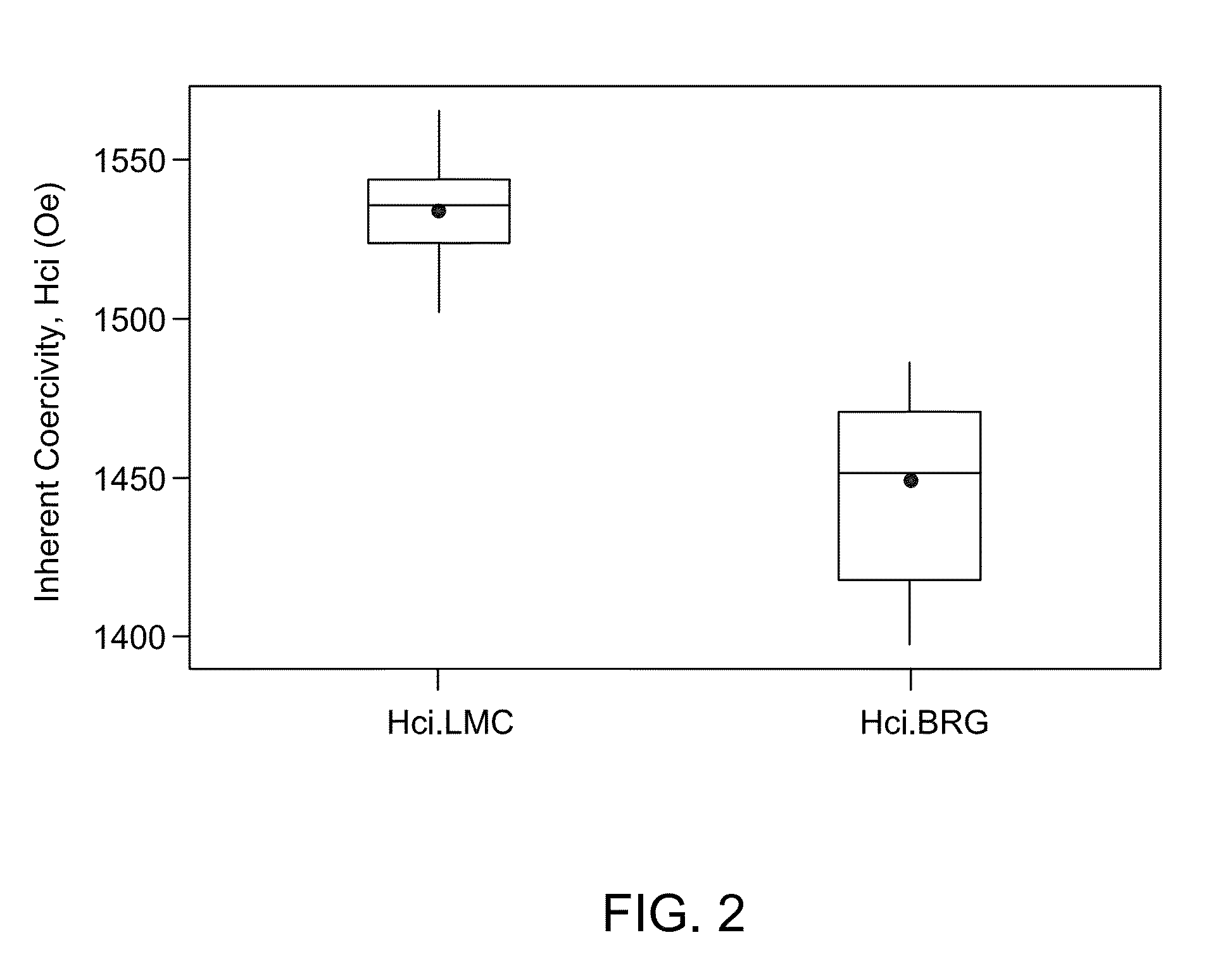
[0034]The effects of heat extraction rate on inherent coercivity (Hci), remanence (Br), and energy product (BH)max are depicted in FIG. 2, FIG. 3, and FIG. 4 respectively. As used herein, LMC stands for liquid metal cooling directional solidification casting and BRG for Bridgman directional solidification casting.

[0035]The inherent coercivity of DS ALNICO castings made via liquid metal coolin...


PUM

PropertyMeasurementUnit
median sizeaaaaaaaaaa
thicknessaaaaaaaaaa

Abstract

A shell mold is described. The shell mold includes a facecoat, a sealcoat, and a support disposed in between the facecoat and the sealcoat. The support includes a stucco in a concentration greater than about 40 volume percent of the support. The stucco includes a material that has a thermal conductivity greater than about 285 W / m-K.

Description

BACKGROUND[0001]The present disclosure generally relates to shell molds for directional casting, and more particularly, to high thermal conductivity shell mold compositions that provide a high heat extraction rate.[0002]In the manufacture of components, such as nickel based superalloy turbine blades and vanes for turbine engines, directional solidification (DS) investment casting techniques have been employed to produce columnar grain and single crystal casting microstructures having improved mechanical properties at the high temperatures encountered in the turbine section of the engine.[0003]For directional solidification of superalloys, the solid-liquid interface applies a high thermal gradient to yield good cast microstructure. In order to provide a high thermal gradient, heat needs to be removed quickly from the solid casting.[0004]Conventional investment shell molds for directional solidification of super alloys and other transition metal-based alloys are made of alumina or zir...

Claims


Application Information

Patent Timeline
Patent Type & Authority Patents(United States)
IPC IPC(8): B22C1/02B22C3/00B22C9/02
CPCB22C1/02B22C3/00B22C9/02B22C9/04B22C13/085
Inventor ZHAO, QIRUTKOWSKI, STEPHEN FRANCISJOHNSON, FRANCISZHANG, WANMINGZOU, MIN
Owner GENERAL ELECTRIC CO
Why Eureka
Try Eureka