Aerosol Laser

a laser and aerosol technology, applied in the field of lasers with high power, can solve the problems of limited transparency range, limited amount of optical power that can be generated, and prone to thermo optic distortion in liquid gain media, so as to reduce optical distortions and widen the spectral window. , the effect of reducing quenching

Inactive Publication Date: 2015-12-15
STATE OF ISRAEL - SOREQ NUCLEAR RES CENT
View PDF2 Cites 0 Cited by
  • Summary
  • Abstract
  • Description
  • Claims
  • Application Information

AI Technical Summary

Benefits of technology

[0007]The present invention seeks to provide a laser in which the lasing material consists of nanoparticles of either a solid-state, liquid or semiconductor lasing material, being in an aerosol phase dispersed in gas, as is described more in detail hereinbelow. The nano-particles result in insubstantial scattering of pump or laser light, while the gas medium lessens substantially the optical distortions induced by non-homogenous pump illumination or non-homogenous flow and low dn / dT, alleviates quenching and allows the laser to operate in a substantially wider spectral window. Therefore the advantages of a nano-particle aerosol laser are more fully achieved and in particular higher power levels can be attained in a wider spectral band without the disadvantage of thermal lensing associated with non-homogeneities in liquid lasers.

Problems solved by technology

A well-known drawback of high power solid state lasers is that they suffer from thermo optic distortions that limit ultimately the amount of optical power that can be generated.
A drawback of this approach is that there must be a close match between the indices of refraction of the solid state particles and the liquid to avoid considerable Mie scattering losses.
These liquid gain media are prone however to thermo optic distortions due, for example, to non-homogeneous pump-light distribution, large index of refraction dependency in temperature (dn / dT) or inhomogeneous flow.
Accordingly, although the use of nanoparticles alleviates the index mismatch problem, there is still a need for improvement because of the abovementioned restrictions, as well as other issues associated with liquid gain media, such as quenching and the limited range of transparency of fluids.

Method used


Image

  • Aerosol Laser
  • Aerosol Laser
  • Aerosol Laser

Examples


Embodiment Construction

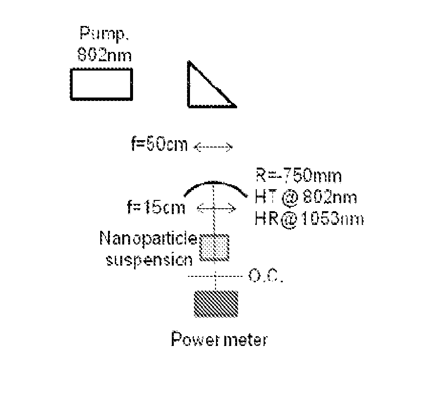
[0017]In general terms, as seen in FIG. 8, the laser device of the invention consists of a laser cavity that encompasses a vessel containing a lasing material being an aerosol of lasant nano-particles suspended in a gas, a pump for supplying laser pump power to the vessel, means for spraying the aerosol (such as a nebulizer), means for circulating the aerosol, e.g., for cooling purposes (such as a fan), means for avoiding aggregation of the particles and maintaining a homogenous particle distribution, and means for coupling the laser beam out of the cavity. Aggregation can be avoided in different ways, such as by using a surfactant that covers each particle, or by transmitting the particles through high voltage electrodes in order to charge the particles and achieve electrostatic rejection, or by heating the pipes to high temperatures to add kinetic energy to the particles that overcomes the adherent forces.

[0018]The lasant nanoparticles, selected for their desired optical and physi...


PUM

PropertyMeasurementUnit
diameteraaaaaaaaaa
decay timeaaaaaaaaaa

Abstract

A laser device including lasing materials composed of nanoparticles in an aerosol phase. One example is Nd2O3 in DMDCS with DMSO which is sprayed into a cuvette, measures have to be taken to prevent for aggregation. The fluorescence life-time is significantly shorter compared to nanoparticles dissolved in a liquid.

Description

FIELD OF THE INVENTION[0001]The present invention relates generally to high power lasers that utilize a gain medium in the aerosol phase.BACKGROUND OF THE INVENTION[0002]A well-known drawback of high power solid state lasers is that they suffer from thermo optic distortions that limit ultimately the amount of optical power that can be generated.[0003]It is also well known that some problems with solid state lasers can be partially solved by the use of a gain medium having a liquid form as described in Patent Applications No US2003 / 0161364 by Michael D. Perry entitled “Laser Containing a Slurry” and No WO2007 / 095246 by Robert R. Rice entitled “Liquid Laser with Colloidal Suspension of Lasant Nanoparticles”.[0004]Perry describes a liquid laser in which the gain medium comprises particles of a solid state material suspended within a fluid having a refractive index substantially similar to that of the particles. This slurry is circulated between a resonator and a cooling system, functio...

Claims


Application Information

Patent Timeline
Patent Type & Authority Patents(United States)
IPC IPC(8): H01S3/16H01S3/03H01S3/094H01S3/223H01S3/23
CPCH01S3/03H01S3/169H01S3/094038H01S3/094076H01S3/1611H01S3/223H01S3/2308
Inventor TZUK, YITSHAK
Owner STATE OF ISRAEL - SOREQ NUCLEAR RES CENT
Why Eureka
Try Eureka