Inflatable and rigidizable support element
a support element and rigidization technology, applied in the field of inflatable and rigidized support elements, can solve problems such as rapid rigidization of support elements
- Summary
- Abstract
- Description
- Claims
- Application Information
AI Technical Summary
Benefits of technology
Problems solved by technology
Method used
Image
Examples
example 1
UV-Curing Source Validation
[0075]Acrylic adhesive requires exposure to UV energy from 200-400 nm at an energy level greater than 5 J per gram of adhesive per second. UV adhesives are typically used in industrial settings where this level of UV radiation is achieved with low pressure mercury vapor lamps, xenon strobes or arrays of high power UV LEDs. Experiments were conducted during development of embodiments of the present invention to identify a mechanism for generating such UV energy in a means amenable to the goals of the present invention (e.g. compact, lightweight), however, the present invention is not limited to any particular mechanism.
Review of Electric-Source UV-Curing Technologies.
[0076]A theoretical comparison of existing UV curing technologies was developed using models of each system. These models used the most advanced components currently available, configured for operation in an aircraft. The figures of merit are specific energy density, volumetric energy density a...
example 2
Wing Structure and Deployment
[0092]In some embodiments, the present invention provides a wing design based on the mechanics of the Manduca sexta moth wing. There are both similarities and differences. The wing design provides utility in a variety of aerial vehicles including, but not limited to commercial aircraft, military aircraft, experimental aircraft, recreational aircraft, lunarcraft, spacecraft, and particularly unmanned aerial vehicles (UAV). The sequence of wing deployment of the Manduca Sexta moth matches with the deployment sequence of an exemplary UAV wing (SEE FIG. 25). A UAV having a greater mass than the moth of requires a longer wingspan that is efficient in soaring flight, and requires an airfoil shape to generate lift with low drag. In some embodiments, the airfoil has an upper and lower wingskin in contrast to the single membrane of the moth wing. In some embodiments, the UAV wingskin is made of a flexible fabric stretched taut over the wing structure (SEE FIG. 26...
example 3
Support Element Design
[0094]The following is an exemplary embodiment of the present invention which should be viewed as illustrative or potential embodiments, and not limiting the scope in any way.
Structural Fiber.
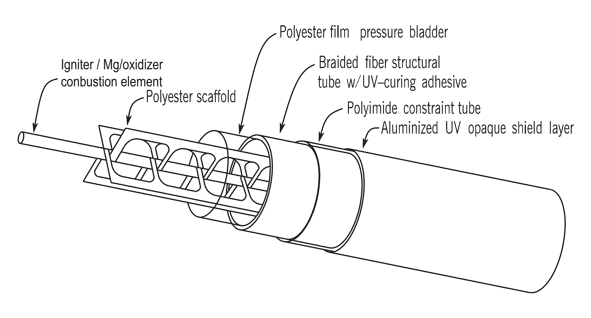
[0095]In some embodiments, UV adhesives require exposure to direct radiation for an effective cure. Composite material using this adhesive is preferably transparent to the particular wavelength. An opaque fiber material (such as carbon fiber) undergoes complete curing on the side exposed to light and unexposed adhesive on the shielded side remains uncured. Common E-grade glass is transparent to near UV but begins blocking wavelengths of 360 nm. KEVLAR is opaque to UV and polyimide is damaged by UV (DuPont Advanced Fiber Systems, “Kevlar Aramid fiber Technical Guide,” Vol. H-77848, 2000; herein incorporated by reference in its entirety). Fused-quartz glass provides a highly suitable structural fiber for UV transmission. Unlike conventional electrical grade borosilicate fibe...
PUM
| Property | Measurement | Unit |
|---|---|---|
| wavelengths | aaaaa | aaaaa |
| wavelengths | aaaaa | aaaaa |
| wavelengths | aaaaa | aaaaa |
Abstract
Description
Claims
Application Information
 - R&D
- Intellectual Property
- Life Sciences
- Materials
- Tech Scout
- Unparalleled Data Quality
- Higher Quality Content
- 60% Fewer Hallucinations
Browse by: Latest US Patents, China's latest patents, Technical Efficacy Thesaurus, Application Domain, Technology Topic, Popular Technical Reports.
© 2025 PatSnap. All rights reserved.Legal|Privacy policy|Modern Slavery Act Transparency Statement|Sitemap|About US| Contact US: help@patsnap.com


