
High-resolution microscope and method for determining the two- or three-dimensional positions of objects

a high-resolution, microscope technology, applied in the field of microscopy, can solve the problems of limited optical resolution of light microscopes such as lsms, limited diffraction by the laws of physics, and rather extensive imaging period, and achieve the above-described method based on localized high resolution only to surfaces and/or 2 dimensions

Active Publication Date: 2016-01-12
CARL ZEISS MICROSCOPY GMBH
View PDF21 Cites 6 Cited by
  • Summary
  • Abstract
  • Description
  • Claims
  • Application Information

AI Technical Summary

Benefits of technology

The invention describes how to create a three-dimensional microscope with improved resolution using advanced technology. High-resolution detection of molecules' axial position can be achieved by using astigmatism / cylinder lenses. This helps to create a better microscope and improve research outcomes.

Problems solved by technology

In principle, the optical resolution of a light microscope, such as a LSM, is limited with regard to diffraction by the laws of physics.
This leads to a rather extensive imaging period as well as to problems with regard to the adjustment of the switching intensity, particularly when the sample and / or the structures of interest are marked very inhomogeneously: in order to prevent losing any information the switching intensity must always be adjusted to the area of the sample marked most densely.
In general, the above-described method based on localized high resolution is limited to surfaces and / or 2 dimensions, because the localization of the individual colorant molecules are considerably more complex in the third dimension (z-direction).
Another problem for the three-dimensional high-resolution display in the depth of a sample lies in the limited penetration depth: as already known from the classical fluorescence microscopy and laser-scanning microscopy, the increasingly dispersed excited radiation in the depth of the sample leads to an increase of the background signals with a simultaneous reduction of the actual wanted signal.
In addition to the undesired photo bleaching of sample sections outside the focused level, it also occurs in the PAL-M method that in the depth of the sample undesired switching of the fluorophores occurs by the activating radiation in the layers not presently measured.

Method used


Image

  • High-resolution microscope and method for determining the two- or three-dimensional positions of objects
  • High-resolution microscope and method for determining the two- or three-dimensional positions of objects
  • High-resolution microscope and method for determining the two- or three-dimensional positions of objects

Examples


Embodiment Construction

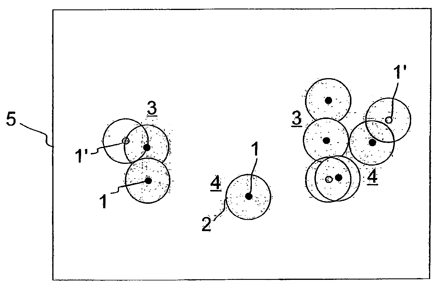
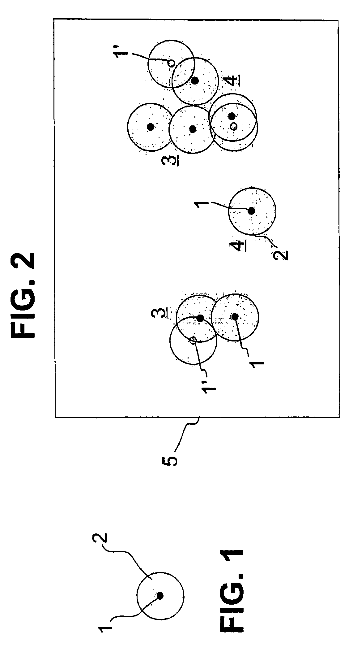
[0082]FIG. 1 shows schematically a marker molecule 1, which has been excited for fluorescence. Of course, the detection of fluorescence requires a plurality of excitations, because each excitation yields precisely one fluorescent proton and the detection of radiation requires an integration of many fluorescent protons. The fluorescent radiation emitted by the marker molecules 1 can be detected in a microscope based on physical principles only in a limited optic resolution. Even if the microscope reaches the diffraction limit of the optic resolution the photons of the fluorescent marker molecule 1 are still distributed due to diffraction and thus detected in a diffraction disk 2. The microscope therefore displays an object principally larger than the geometric extension of the marker module 1, drawn in FIG. 1 schematically as a black circle, which is illustrated in FIG. 1 by the diffraction disk 2. The size of the diffraction disk 2 depends on the quality of the microscopy device use...


PUM

PropertyMeasurementUnit
wavelengthaaaaaaaaaa
thicknessaaaaaaaaaa

Abstract

The invention relates to a high-resolution microscope and to a method for determining the two- or three-dimensional positions of objects. The microscope and method includes the following: (a) The vertical (Z) position of imaged particles or molecules being determined from the orientation and shape thereof by means of an anamorphic lens, preferably a cylindrical lens, in the imaging, (b) the detection beam path being split into at least two partial detection beam paths having different optical path lengths, which are detected at an offset on a detector, (c) activation or switchover being performed by means of a multi-photon excitation process, preferably two-photon excitation. The following are also included: (d) a point-scanning activation or switchover, (e) a line-scanning activation or switchover, (f) the sample is excited and the sample light is detected in the wide-field mode, (g) manually or automatically predetermined sample regions are activated or switched over, (h) the activation or switchover is performed by means of AOTF or SLM or DMD, (i) laser pulses for activating or switching are spectrally split by means of a spectrally splitting element, preferably a grating, (j) an SLM or DMD in the beam path after the grating performs a controlled selection of split laser pulse fractions, (k) the laser wide-field excitation is guided by SLM or DMD, (l) ROIs are selected by SLM or DMD, (m) a multi-photon switching or activation is performed by means of a microlens array, preferably a cylindrical lens array, n) switching and / or excitation is performed by means of a line scanner, and (o) a line detection is performed by means of a spatially resolved sensor, wherein at least two sensor rows, each comprising a plurality of sensors, are illuminated with sample light by means of a slit diaphragm position.

Description

RELATED APPLICATIONS[0001]The present application is a U.S. National Stage application of International PCT Application No. PCT / EP2010 / 007595 filed on Dec. 14, 2010 which claims priority benefit of German Application No. DE 10 2009 060 793.5 filed on Dec. 22, 2009, the contents of each are incorporated by reference in their entirety.FIELD OF THE INVENTION[0002]The present invention relates generally to the field of microscopy and more particularly to high-resolution microscopy.BACKGROUND OF THE INVENTION[0003]In principle, the optical resolution of a light microscope, such as a LSM, is limited with regard to diffraction by the laws of physics. For an optimal resolution within these limits particularly illumination configurations are known, such as 4Pi arrangements or arrangements with fields of stationary waves. Here, the resolution can be considerably improved, particularly in the axial direction, in reference to classic LSM.[0004]Using non-linear depopulation processes, the resolu...

Claims


Application Information

Patent Timeline
Patent Type & Authority Patents(United States)
IPC IPC(8): G01N21/64G02B27/58G02B21/36G02B21/16
CPCG01N21/6458G01N21/6428G02B21/16G02B21/361G02B21/367G02B27/58
Inventor KALKBRENNER, THOMASWOLLESCHENSKY, RALF
Owner CARL ZEISS MICROSCOPY GMBH
Learn More