Charging system for battery-powered unmanned aerial vehicles

a charging system and aircraft technology, applied in the field of aircraft, can solve the problems of charging capabilities, etc., and achieve the effects of increasing the efficiency of such operations, increasing the cost feasibility of operating these aircraft, and efficient and customizable charging configurations

Active Publication Date: 2016-01-19
THE BOEING CO
View PDF12 Cites 20 Cited by
  • Summary
  • Abstract
  • Description
  • Claims
  • Application Information

AI Technical Summary

Benefits of technology

[0007]Example implementations the present disclosure are generally directed to an apparatus and method for the simultaneous storage and charging of multiple battery-powered aircraft such as unmanned aerial vehicles (UAVs), and without removal of their batteries. The storage capabilities may allow more UAVs per operator and mission, and may increase the efficiency of such operation. The charging capabilities may increase the cost feasibility of operating these aircraft, such as by using less equipment than may otherwise be required to individually charge multiple UAVs in a given period of time. Example implementations may additionally provide safety protection, as well as efficient and customizable charging configurations for quickly charging these aircraft and reduced manual labor that may otherwise be required to remove their batteries for charging.

Problems solved by technology

The charging capabilities may increase the cost feasibility of operating these aircraft, such as by using less equipment than may otherwise be required to individually charge multiple UAVs in a given period of time.

Method used


Image

  • Charging system for battery-powered unmanned aerial vehicles
  • Charging system for battery-powered unmanned aerial vehicles
  • Charging system for battery-powered unmanned aerial vehicles

Examples


Embodiment Construction

[0034]Some implementations of the present disclosure will now be described more fully hereinafter with reference to the accompanying drawings, in which some, but not all variations of the disclosure are shown. Indeed, variations of the disclosure may be embodied in many different forms and should not be construed as limited to the examples set forth herein; rather, these are provided so that this disclosure will be thorough and complete, and will fully convey the scope of the disclosure to those skilled in the art. For example, reference may be made herein to values of or relationships between components, parameters, properties, variables or the like. These and other similar values or relationships may be absolute or approximate to account for variations that may occur, such as those due to engineering tolerances or the like. Like reference numerals refer to like elements throughout.

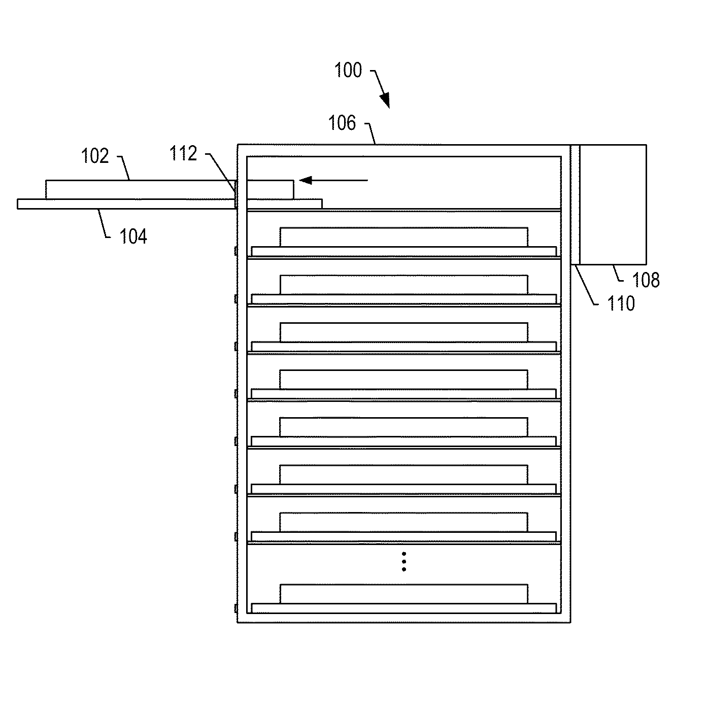
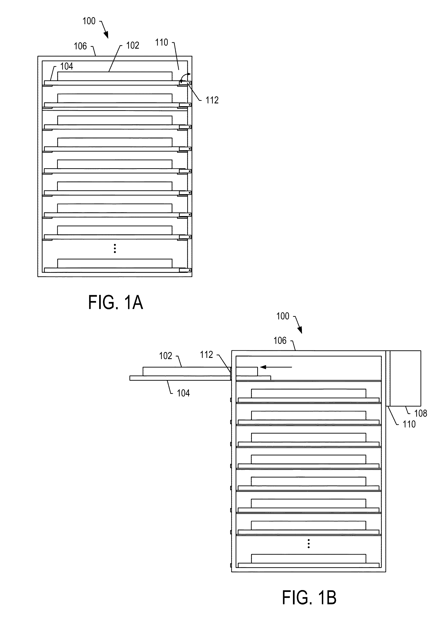
[0035]FIGS. 1A and 1B (collectively FIG. 1) illustrate schematic block diagrams of front and side vie...


PUM


Abstract

A rack system is provided that includes a plurality of trays configured to hold a respective plurality of battery-powered UAVs, and a frame configured to support the plurality of trays in a vertical arrangement. Each tray of the plurality of trays includes a platform, bumper and first plurality of electrical contacts. The platform may be configured to carry a UAV of the plurality of battery-powered UAVs. The bumper may be sized and positioned on the platform to guide the UAV to a resting position on the platform. And the first plurality of electrical contacts may be connected to a battery-charging apparatus, and configured to physically and electrically contact a respective second plurality of electrical contacts connected to a respective plurality of batteries on the UAV at the resting position on the platform. A related battery-charging apparatus including a charge switching system for charging battery-powered UAVs is also provided.

Description

TECHNOLOGICAL FIELD[0001]The present disclosure relates generally to aircraft and, in particular, to a charging system for battery-powered aircraft.BACKGROUND[0002]An unmanned aerial vehicle (UAV) is an aircraft that flies without human operators being present in the aircraft. These UAVs may be controlled from a remote location. At this remote location, a human operator or a program executed by a computer generates commands for the UAV. Or in other examples, a program running on a computer or other controller on the UAV may generate commands for the UAV.[0003]UAVs may be used for a number of different purposes. Currently, the largest use is for military applications, such as reconnaissance missions, attack missions or other suitable types of missions. UAVs also may be used in a number of civilian applications, such as to perform surveying, firefighting or other suitable types of missions. In one more particular example of a civilian application, UAVs may be used in agricultural appl...

Claims


Application Information

Patent Timeline
Patent Type & Authority Patents(United States)
IPC IPC(8): H02J7/00H02J3/10H02J1/00H02J1/08H02J1/10B60L11/18H02J3/14H02J7/14
CPCB60L11/1809B60L11/1822B60L2200/10Y02T10/7005Y02T10/7072Y02T90/14B60L53/00B60L53/80Y02T10/70Y02T90/12
Inventor RYBERG, CAITLINQUADRACCI, LEONARD J.
Owner THE BOEING CO
Why Eureka
Try Eureka