Apparatus for parallel operation of pulse-width modulation power converters

a technology of power converters and parallel operation, applied in the direction of electrical apparatus, power conversion systems, control systems, etc., can solve the problems of unstable operation, loss of linearity of current,

Active Publication Date: 2016-02-09
MEIDENSHA ELECTRIC MFG CO LTD
View PDF18 Cites 7 Cited by
  • Summary
  • Abstract
  • Description
  • Claims
  • Application Information

AI Technical Summary

Benefits of technology

[0022]Since reset windup is generated because of too much increase of the integral action, the system performs the auto adjusting PI control restraining the integral action, and decreases the operation quantity due to the integration in accordance with the amount of the operation quantity cut off by the saturation. Consequently, the system can improve the operation quantity and the response, and improve the settling time.
[0027]According to the present invention, in the PWM power converter parallel running apparatus, it is possible to perform an anti-windup control properly without interference with a cross current compensating function, even in case of voltage saturation.

Problems solved by technology

Moreover, if the voltage is generated forcibly, the time of limitation of the voltage limit values is increased, and hence, the current loses the linearity so that the operation becomes unstable.
However, if the output voltage is limited, the deviation is not decreased, and the integral control action is carried out excessively so as to amplify the voltage commands Vd_cmd and Vq_cmd.
As a result, the linearity of the current is lost.
This loss is an unavoidable loss caused by the saturation.
If the unintended torque vibration becomes equal to the machine resonance frequency, the torque at this frequency is amplified, and the machine system might be damaged.

Method used


Image

  • Apparatus for parallel operation of pulse-width modulation power converters
  • Apparatus for parallel operation of pulse-width modulation power converters
  • Apparatus for parallel operation of pulse-width modulation power converters

Examples


embodiment 1

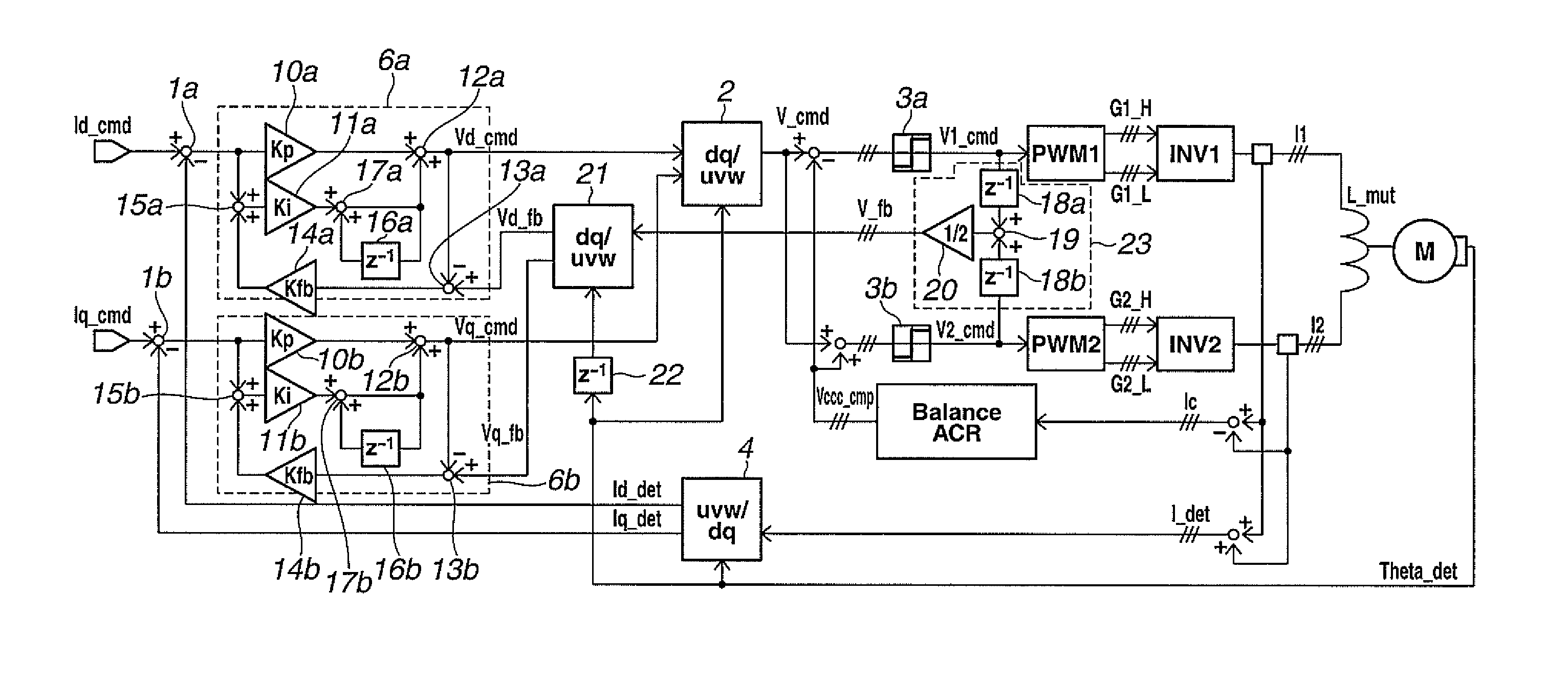
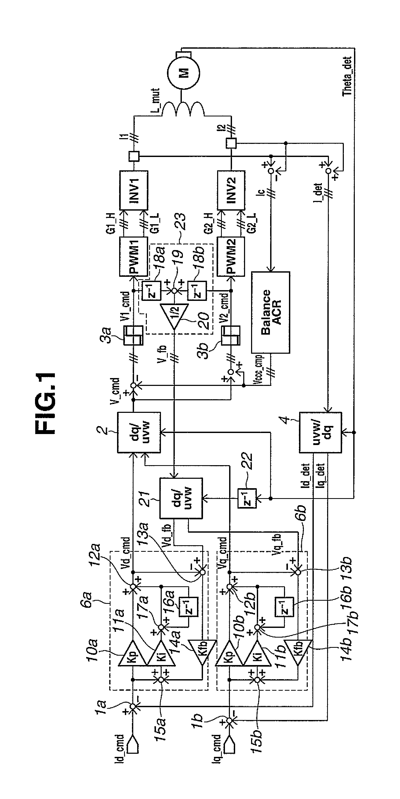
[0035]FIG. 1 is a block diagram showing a PWM power converter parallel running apparatus according to Embodiment 1.

[0036]First, a subtracting section 1a determines a deviation of a d-axis current command value or quantity Id_cmd from a d-axis current detection value or quantity Id_det, and an output current control section 6a performs a PI control. Similarly, a subtracting section 1b determines a deviation of a q-axis current command value or quantity Iq_cmd from a q-axis current detection value or quantity Iq_det, and an output current control section 6b performs a PI control. A dq inverse transformer 2 inversely transforms voltage commands Vd_cmd and Vq_cmd which are outputs of the output current control sections 6a and 6b, into a voltage command V_cmd.

[0037]The dq transformation and the dq inverse transformation are expressed by a following mathematical expression (1). In the mathematical expression (1), θ represents a phase.

[0038][Math.⁢1][Cdq]=23⁡[cos⁢⁢θsin⁢⁢θ-sin⁢⁢θcos⁢⁢θ]·[1-...

embodiment 2

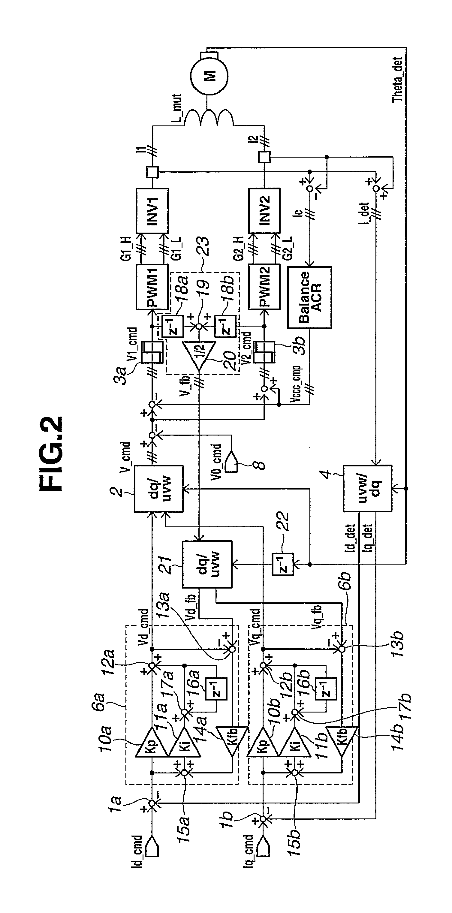
[0055]A PWM power converter parallel running apparatus according to Embodiment 2 is arranged to perform a zero phase modulation to increase a voltage output range unlike the PWM power converter running apparatus according to Embodiment 1.

[0056]FIG. 2 is a block diagram showing the PWM power converter parallel running apparatus according to Embodiment 2. Among various methods proposed as the zero-phase modulation, the following explanation employs, as an example, a method of Patent Document 2. The voltage command V_cmd of each phase is subjected to subtraction of a zero-phase voltage command V0_cmd which is a sine wave having a frequency equaling a triple of a frequency of a fundamental wave. In the example of FIG. 2, the cross current compensation is performed after the subtraction of the zero-phase voltage command V0_cmd from the voltage command V_cmd. The d-axis and q-axis feedback quantities Vd_fb and Vq_fb can be determined in the same operation as in Embodiment 1. The d-axis an...

embodiment 3

[0058]A PWM power converter parallel running apparatus according to Embodiment 3 is arranged to add a dead time compensation to the PWM power converter running apparatus according to Embodiment 2.

[0059]For explanation of the dead time compensation, FIG. 4 shows a time chart of the dead time compensation. FIG. 4 shows the time chart of inverter INV1 only. First, an error time measurement value or quantity Vce_DLY1 is a value determined by measurement between the gate command Gate1 and an inverter phase voltage detection value or quantity Vce1 at the on time and the off time. In order to use the error time measurement quantity Vce_DLY1 for the dead time compensation, a dead time compensating section 9 obtains a dead time compensating voltage Vdtc_cmp1 [p.u.] which is a quantity obtained by converting the error time measurement quantity Vce_DLY1 to the form in the unit (voltage) identical to the unit of the voltage command quantity V_cmd [p.u.]. This dead time compensating voltage Vdtc...


PUM


Abstract

To perform an anti-windup control without interference with a cross current compensating function even in case of voltage saturation.There is provided a feedback value calculating section to calculate an average of voltage commands V1_cmd, V2_cmd after output limitation, as a feedback value. As a deviation used for an integral calculation of a current control section 6a, 6b, a sum obtained by adding a product to a deviation between a current command value Id_cmd, Iq_cmd and a current detection value Id_det, Iq_det is used. The product is a quantity obtained by multiplying a saturation quantity by a feedback gain Kfb. The saturation quantity is a saturation quantity of an operation quantity limited by a voltage command limiting section 3a, 3b, and the saturation quantity is a deviation or difference between a feedback value V_fb (Vd_fb, Vq_fb) and the voltage command Vd_cmd.

Description

TECHNICAL FIELD[0001]The present invention relates to an operation method or technique for operating power converters using PWM control, and more specifically to operation at the time of voltage saturation in the case of parallel connection of power converters.BACKGROUND ART[0002]In order to increase the capacity of a power conversion system such as a motor drive apparatus, there is a need for increasing the capacity of a power converting apparatus. One known technique for increasing the capacity of the power converting apparatus is arranged to operate a plurality of power converters in parallel connection and to provide, to a motor, a sum of output powers of the power converters.[0003]In one technique for the parallel operation of power converters, power converters are connected, through one or more reactors or interphase reactors, with a motor. In the case of a common power source common to the parallel connected power converters, there arises a voltage difference due to nonunifor...

Claims


Application Information

Patent Timeline
Patent Type & Authority Patents(United States)
IPC IPC(8): H02M7/48H02M7/493H02P27/08
CPCH02P27/085H02M7/493
Inventor HAMADA, SHIZUNORITAKAHASHI, TOSHIMICHI
Owner MEIDENSHA ELECTRIC MFG CO LTD
Why Eureka
Try Eureka