Eureka AIR delivers breakthrough ideas for toughest innovation challenges, trusted by R&D personnel around the world.

Spherical liquid-crystal laser

a liquid crystal laser and spherical technology, applied in the direction of lasers, liquid crystal laser construction details, laser construction details, etc., can solve the problem of large temperature sensitivity of the amplitude of stimulated emission of spherical resonators

Active Publication Date: 2016-02-16
INSTITUT JOZEF STEFAN
View PDF3 Cites 0 Cited by
  • Summary
  • Abstract
  • Description
  • Claims
  • Application Information

AI Technical Summary

Benefits of technology

The present invention provides a microscopic source of laser light that can be integrated into optical integrated circuits and used for lighting objects, microscopy, display technology, holography, and other applications. The laser source needs to be coherent and emit light of a single wavelength that is connected in phase. It can also be emitted in all directions or in specific directions, and its wavelength can easily be changed. The laser source includes one or more droplets of chiral liquid crystals that have been enveloped by a thin layer or filled with another substance that does not allow the liquid crystals to move to the exterior. The liquid crystals inside the droplets are arranged in a helical structure, which causes a periodic variation of the directions of the main axes of the dielectric tensor in the radial direction and optical properties of the droplet in the radial direction. The centrally arranged droplets can have a point defect or a defect line and can influence the parameters of lasing. Thus, the laser-active material can be placed in the center of the droplet, allowing for control over lasing.

Problems solved by technology

The technical weakness of the proposed spherical laser is thus the large temperature sensitivity of the amplitude of the stimulated emission of the spherical resonator with a surface reflector, which is a result of the resonator's temperature elongation.

Method used


Image

  • Spherical liquid-crystal laser
  • Spherical liquid-crystal laser
  • Spherical liquid-crystal laser

Examples


Embodiment Construction

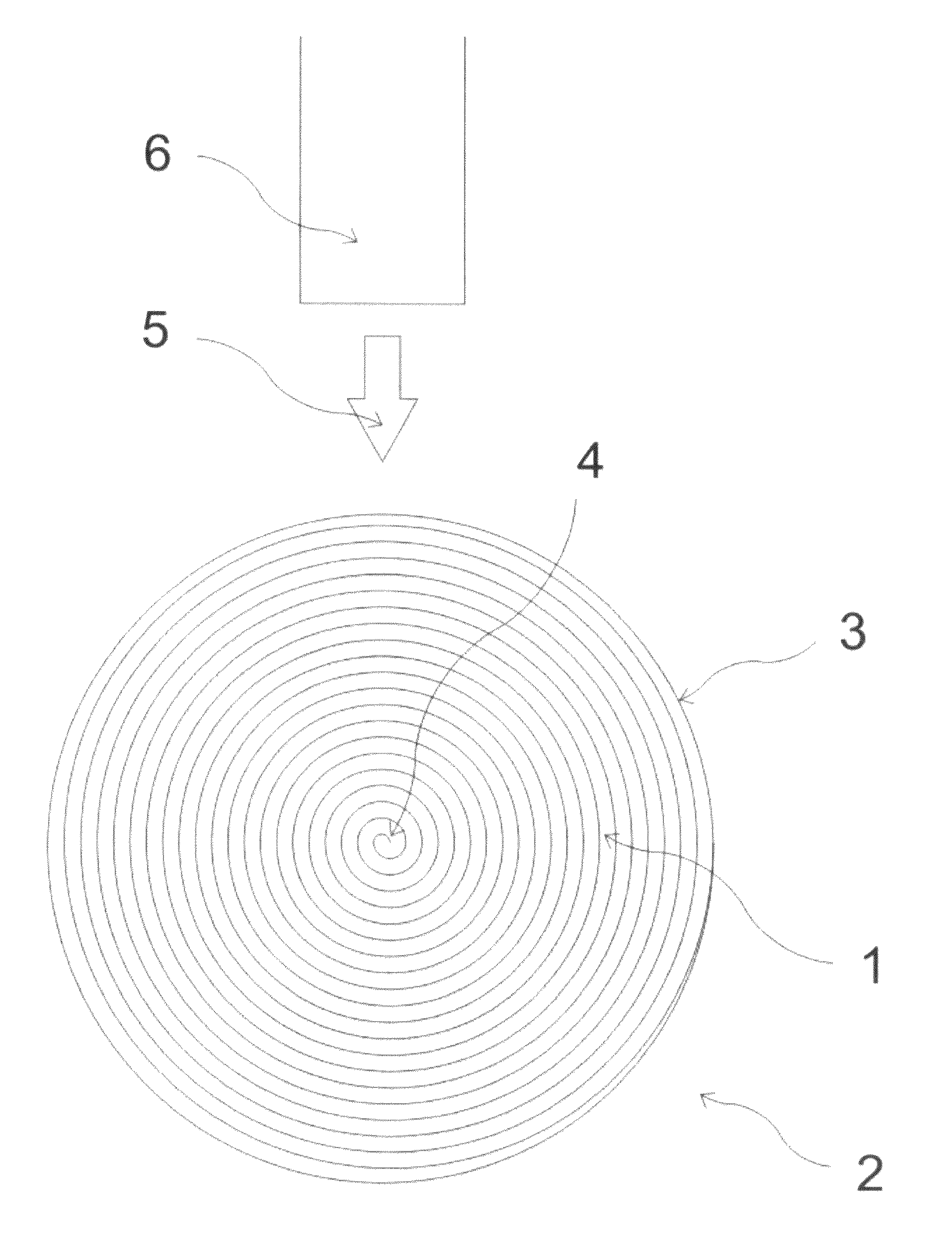
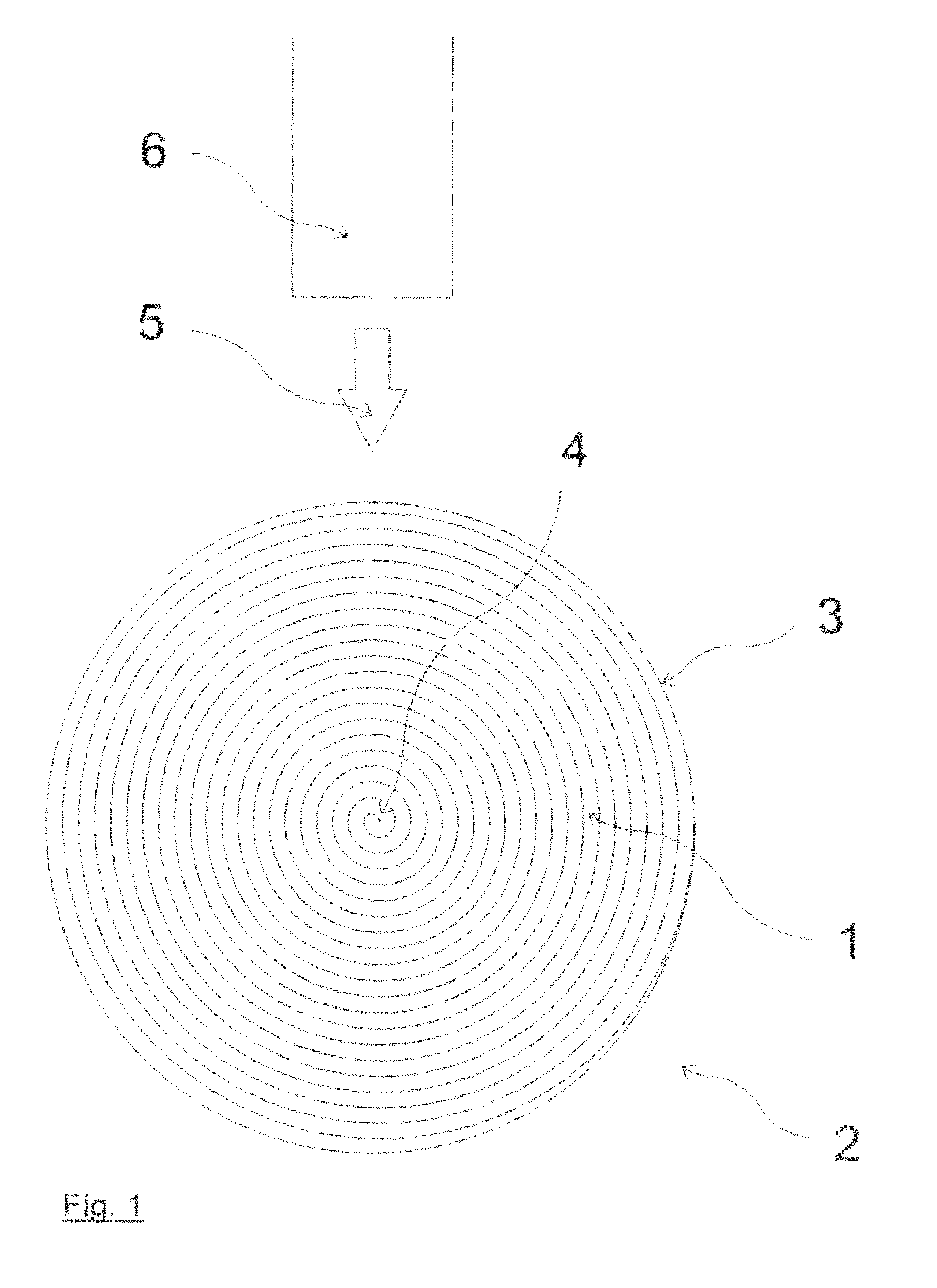
[0031]FIG. 1 schematically presents the basic spherical liquid-crystal laser common to all the presented variations. The spherical liquid-crystal laser is made in the shape of a droplet with helically arranged liquid crystals 1 placed in a transparent external medium 2 with an optically clear boundary 3 between the two elements. Due to the surface tension the droplet of cholesteric liquid crystals is shaped into a completely spherical droplet in the external liquid medium. The droplet size is preferable in the range between a few nanometers and 100, μm. Droplets can be formed by the mechanical mixing of liquid crystals and an external liquid medium or by the well-known procedures of phase separation during polymerisation or photo-polymerisation of the supporting optically isotropic medium, in which the liquid-crystal droplets are distributed.

[0032]The boundary between the external substance and the inside of a droplet is formed in such a way that the molecules of the liquid crystals...


PUM


Abstract

The patent refers to one or more droplets of chiral liquid crystals used as point source(s) of laser light. The source is shaped as a droplet of chiral liquid crystals (1) and an active medium preferably dispersed in the liquid crystals. The source is spherical and with a size of preferably between a few nanometres and 100 micrometres. A droplet consists of chiral liquid crystals (1) that have selective reflection in the range of the active medium's emission and can be cholesteric liquid crystals, a mixture of nematic liquid crystals and a chiral dopant or any other chiral liquid-crystal phase, preferably the blue phase, the ferroelectric phase, the antiferroelectric phase, any of the ferrielectric phases or another chiral phase of a soft substance, that need not be chiral by itself.

Description

CROSS-REFERENCE TO RELATED APPLICATION[0001]This is a §371 application of International patent application number PCT / EP2011 / 005607, filed Nov. 8, 2011, which claims the benefit of Slovenian patent application number P201000377 filed on Nov. 10, 2010, both of which are incorporated herein by reference.TECHNICAL FIELD[0002]The invention is intended for producing lasers, more specifically, the area of producing dye lasers.BACKGROUND ART[0003]Modern technology for producing microelectronic and optoelectronic circuits allows the efficient production of microlasers. Diode semi-conducting microlasers are especially well known, as they are the most frequently used type of lasers. When charged with electricity the thin layer around the semi-conducting p-n junction functions as an active medium emitting light. This active laser region has to be within the resonant cavity that can be made in several different ways. With respect to the type of resonator, the main types of semi-conducting laser...

Claims


Application Information

Patent Timeline
IPC IPC(8): H01S3/06H01S3/16H01S3/14H01S3/02H01S3/106H01S3/105H01S3/102
CPCH01S3/022H01S3/0627H01S3/1686H01S3/1028H01S3/1053H01S3/1065H01S3/06H01S3/102H01S3/16
Inventor MUSEVIC, IGORHUMAR, MATJAZ
Owner INSTITUT JOZEF STEFAN
Why Eureka
Eureka Blog
Learn More