
Exhaust system for a vehicle having a “stop-start” compression ignition engine

a technology of compression ignition and exhaust system, which is applied in the direction of metal/metal-oxide/metal-hydroxide catalyst, physical/chemical process catalyst, separation process, etc., can solve the problems of diesel oxidation catalyst (doc) not being able to achieve or maintain “light-off” and relatively cool exhaust gases, so as to improve activity and treat cold-start emissions as quickly

Active Publication Date: 2016-03-01
JOHNSON MATTHEY PLC
View PDF39 Cites 2 Cited by
  • Summary
  • Abstract
  • Description
  • Claims
  • Application Information

AI Technical Summary

Benefits of technology

This patent is discussing a new technology for treating exhaust gas in diesel engines that use stop / start technology. With this technology, the engine is constantly starting and stopping, which leads to less variation in catalyst temperature during the driving cycle. The inventors have designed a new diesel oxidation catalyst that is more effective in treating emissions from these types of engines. The new catalyst is able to balance the need to quickly treat cold-start emissions with the need to maintain catalyst activity during cooler periods of the driving cycle.

Problems solved by technology

However, under certain circumstances low exhaust gas temperatures can mean that the Diesel Oxidation Catalyst (DOC) may be unable to operate effectively.
That is, the DOC may be unable to achieve or to maintain “light-off”.
For vehicles not fitted with an engine “stop-start” system, an additional problem arising from operation of the engine under such light load conditions is that whilst the engine is operating, relatively cool exhaust gases, comprising mostly air, continue to pass from the engine through the DOC or other catalyst.
When load is reapplied, for example upon acceleration, the catalyst is unable to meet the desired conversion of the pollutant gases immediately, with the result that emissions of pollutants may be above the regulated levels for a period.

Method used


Image

  • Exhaust system for a vehicle having a “stop-start” compression ignition engine
  • Exhaust system for a vehicle having a “stop-start” compression ignition engine

Examples


example

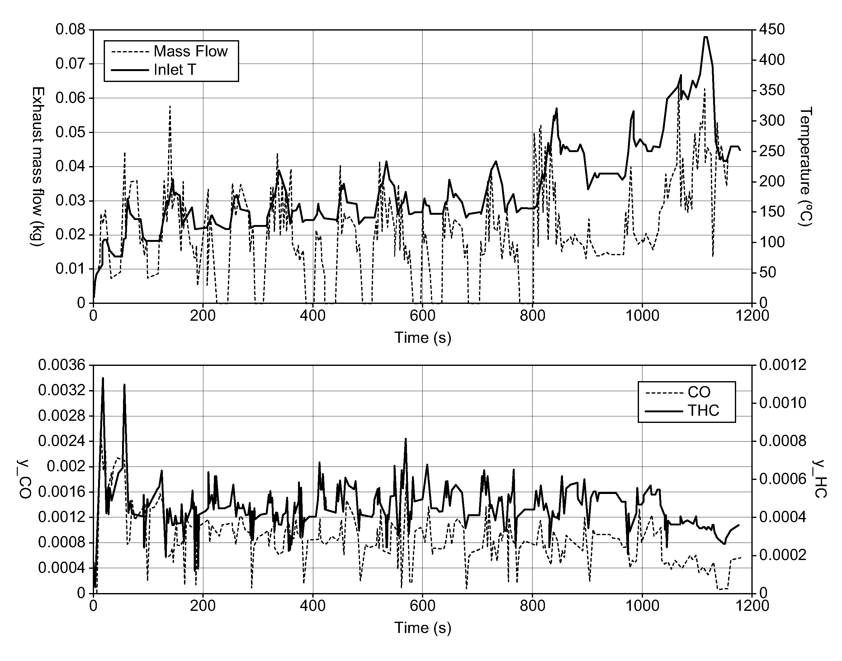
[0028]The following Example represents the results of a computer model, wherein a cylindrical 400 cells per square inch cordierite flow-through honeycomb monolith substrate having dimensions 143×98×135 mm and a volume of 1.50 L is coated throughout with an homogeneous Diesel Oxidation Catalyst washcoat layer of low (2.5 gin−3) or high (7.0 gin−3) washcoat loading and a uniform platinum loading (Comparative Example). Zoned Diesel Oxidation Catalysts according to the invention were prepared using the same bare honeycomb substrate monolith and are shown in Table 1.

[0029]Methods of preparing zoned honeycomb substrate monoliths are known in the art and include the Applicant's WO 99 / 47260, i.e. comprising the steps of (a) locating a containment means on top of a support, (b) dosing a pre-determined quantity of a liquid component into said containment means, either in the order (a) then (b) or (b) then (a), and (c) by applying pressure or vacuum, drawing said liquid component into at least...


PUM

PropertyMeasurementUnit
temperaturesaaaaaaaaaa
densityaaaaaaaaaa
volumeaaaaaaaaaa

Abstract

A vehicle comprises a compression ignition engine provided with engine management means and having a catalyst for exhaust gas aftertreatment, wherein the engine management means is configured, when in use, to detect idle conditions and upon determining that idle conditions exist, stops the engine entirely, wherein the catalyst comprises a honeycomb substrate monolith coated with a catalytic washcoat comprising one or more precious metal, which catalytic washcoat being arranged between a first, upstream washcoat zone and a second, downstream washcoat zone, wherein a thermal mass in the first washcoat zone is different from a thermal mass in the second washcoat zone and wherein a washcoat layer in the first, upstream washcoat zone is substantially contiguous with a washcoat layer in the second, downstream washcoat zone.

Description

CROSS-REFERENCE TO RELATED APPLICATIONS[0001]This application claims priority of British Patent Application No. GB 0922194.6, filed on Dec. 21, 2009, the disclosure of which is incorporated herein by reference in its entirety for all purposes.FIELD OF THE INVENTION[0002]The present invention relates to an exhaust system for a vehicular compression ignition internal combustion engine, such as a Diesel engine, and in particular it relates to an exhaust system for a vehicle comprising a so-called engine “stop-start” system.BACKGROUND OF THE INVENTION[0003]The emissions from vehicles and internal combustion engines generally are the subject of ever-tightening regulation around the world. Concern about global warming associated with CO2 emissions has led to fiscal incentives in a number of countries to reduce CO2 emissions from vehicles. Increasingly, therefore, private cars and light commercial vehicles are being powered by light duty diesel engines, which have relatively low fuel consu...

Claims


Application Information

Patent Timeline
Patent Type & Authority Patents(United States)
IPC IPC(8): F01N3/00B01J23/44B01J23/48B01J23/40F01N3/28F02N11/08
CPCF01N3/2828F01N3/281F01N2330/60F01N2510/0682F02N11/0814B01J23/40B01J23/44B01J23/48B01J23/66B01J23/54B01D53/945Y02A50/20F01N3/0814B01J35/19
Inventor BERGEAL, DAVIDPHILLIPS, PAUL, RICHARD
Owner JOHNSON MATTHEY PLC
Learn More