
Disposable, miniature internal optical ignition source for ammunition application

a technology of internal optical ignition source and ammunition, which is applied in the direction of ammunition fuzes, cartridge ammunition, weapons, etc., to achieve the effects of reducing the risk of inadvertent initiation, reducing the threat, and reducing the sensitivity

Active Publication Date: 2016-03-01
UNITED STATES OF AMERICA THE AS REPRESENTED BY THE SEC OF THE ARMY
View PDF4 Cites 9 Cited by
  • Summary
  • Abstract
  • Description
  • Claims
  • Application Information

AI Technical Summary

Benefits of technology

The present invention is about using a laser diode to create a reliable and easily available light source for a primer assembly or ignition system. This system can be easily integrated into existing weapon hardware without affecting their performance or functionality. Additionally, this system has the advantage of being resistant to accidental ignition from electromagnetic interference.

Problems solved by technology

As can be appreciated, locating a laser ignition system in the breech of an artillery system presents numerous challenges.
Among the most difficult of these challenges are those related to making the laser ignition system sufficiently robust to endure the continuous extreme vibration, shock and thermal excursions produced by the weapon system when fired, as well as the extreme environmental conditions such as long term storage and operation in hot or cold and wet or dry weather conditions.

Method used


Image

  • Disposable, miniature internal optical ignition source for ammunition application
  • Disposable, miniature internal optical ignition source for ammunition application
  • Disposable, miniature internal optical ignition source for ammunition application

Examples


Embodiment Construction

[0022]The following merely illustrates the principles of the invention. It will thus be appreciated that those skilled in the art will be able to devise various arrangements which, although not explicitly described or shown herein, embody the principles of the invention and are included within its spirit and scope.

[0023]Furthermore, all examples and conditional language recited herein are principally intended expressly to be only for pedagogical purposes to aid the reader in understanding the principles of the invention and the concepts contributed by the inventor(s) to furthering the art, and are to be construed as being without limitation to such specifically recited examples and conditions.

[0024]Moreover, all statements herein reciting principles, aspects, and embodiments of the invention, as well as specific examples thereof, are intended to encompass both structural and functional equivalents thereof. Additionally, it is intended that such equivalents include both currently kno...


PUM


Abstract

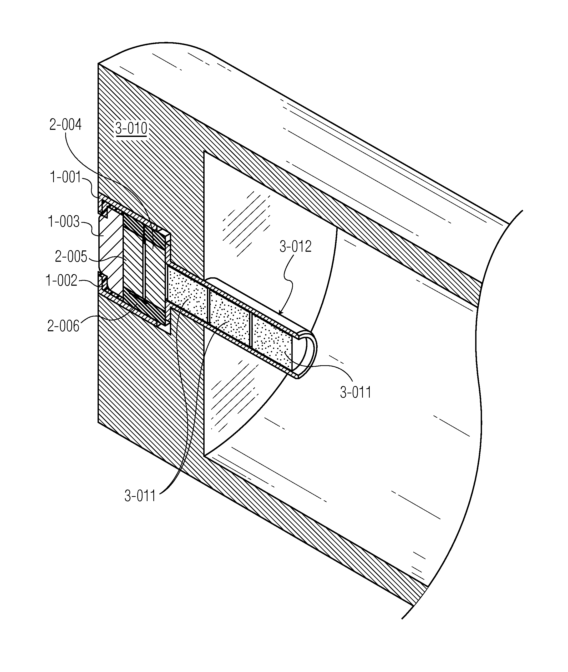
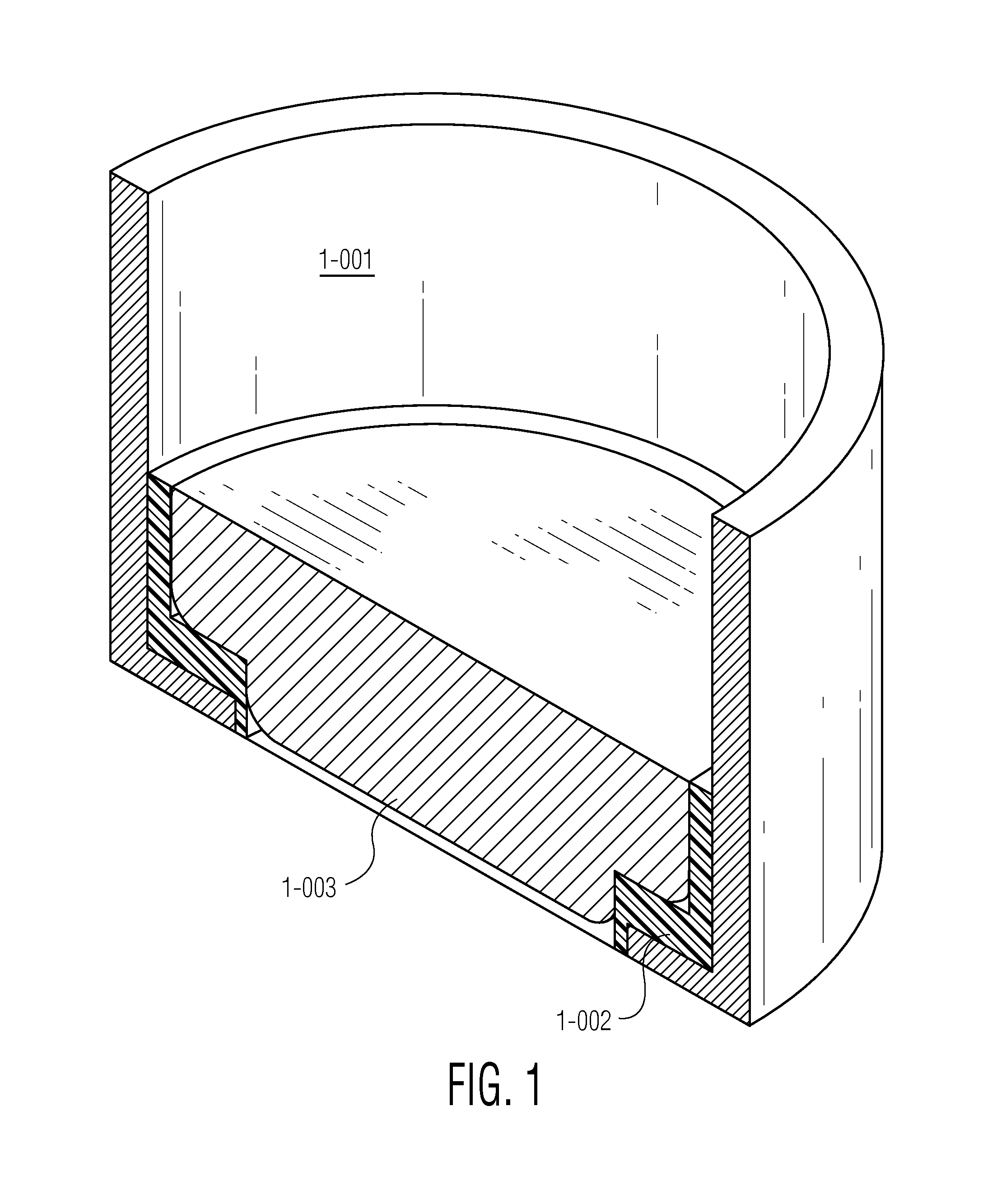
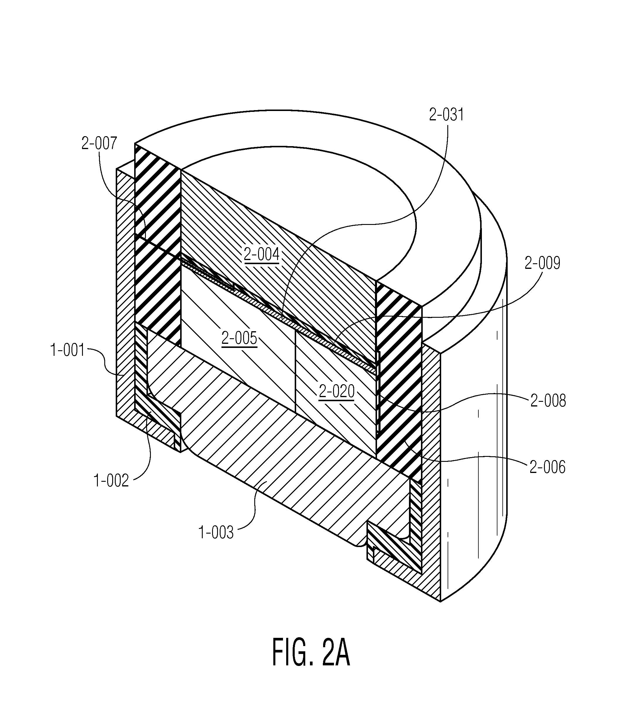
An ammunition cartridge for a gun is optically initiated by a mechanism wholly within the cartridge case itself. The case has as optical primer initiation means producing light fluence to ignite a primer, which ignited primer may in turn ignite into a flashtube, and which ignited flashtube may in turn ignite a bed of propellant in said cartridge. The optical primer initiation means may be an LED, a laser diode, a VCSEL, or some other light emitting device in general. The cartridge optically initiated primer package is so sized and made electrically and mechanically seamlessly physically compatible with current ammunition cartridges such that these new cartridges are completely interchangeable. If the cartridge primer initiation means is of a percussion type, the cartridge is adapted to include an in-line piezoelectric crystal so that electrical power will be generated when the cartridge assembly is struck by a firing pin during percussion type operations; the power is then used to initiate the light emitting device.

Description

CROSS REFERENCE TO RELATED APPLICATION[0001]This application claims benefit of provisional application 61 / 806,086 filed Mar. 28, 2013, the entire file wrapper contents of which application are hereby incorporated by reference as if set forth at length.FEDERAL INTEREST STATEMENT[0002]The inventions described herein may be manufactured, used and licensed by or for the United States Government for United States Government purposes.BACKGROUND AND FIELD OF THE INVENTION[0003]This invention relates generally to the field of the ignition of small, medium and large caliber munitions and specifically to the use of an optical source (laser or other light emitting source) contained within the base of each cartridge case in place of the traditional chemical primer. Most conventional cartridge systems are initiated by use of a center fire based primer within a metal casing. Such primers are typically initiated through electrical, mechanical or optical means. These systems in particular are used ...

Claims


Application Information

Patent Timeline
IPC IPC(8): F42B5/08
CPCF42B5/08F42C19/0807F42C19/14
Inventor BURKE, GREGORY, C.HIRLINGER, JOHN, M.
Owner UNITED STATES OF AMERICA THE AS REPRESENTED BY THE SEC OF THE ARMY
Learn More