
Electrode structure for touchscreen

a touchscreen and electrode technology, applied in the direction of instruments, circuit optical details, metal adhesion improvement of the insulating substrate, etc., can solve the problems of high resistance, low efficiency, and deformation of the electrode surface, and achieve the effect of reducing the metallic luster

Inactive Publication Date: 2016-03-08
J TOUCH CORPORATION
View PDF23 Cites 2 Cited by
  • Summary
  • Abstract
  • Description
  • Claims
  • Application Information

AI Technical Summary

Benefits of technology

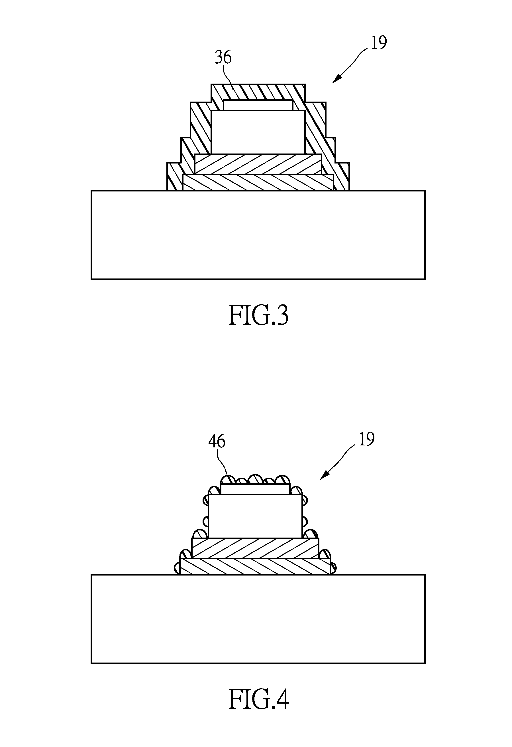
The patent text describes an electrode structure for touchscreen that can be attached to flexible substrates firmly and reduce metallic luster. The structure includes a first resist layer that covers the conductive layer and other layers on the flexible substrate, a second resist layer that reflects light to make it anti-reflective, and an adhesive layer to enhance adhesion. The structure also has a cascading surface that scatters light and reduces visibility. The technical effects of the invention are strong adhesion to flexible substrates, firm attachment of the conductive layer to the substrate, and improved visibility.

Problems solved by technology

However, with the gradual development to the large-size touch panel, some defects of ITO electrodes are emerged such as high resistance, slow response and etc.
In general, the touch panel using metal conductor as the electrodes often occurs the electrodes peeling due to the bad adhesion between the metal conductor and the common substrate, thereby affecting the performance of the touch panel.
If applied to the flexible touch panel, it will exacerbate the occurrence of electrode peeling because the substrate is frequently deformed by the change of the environmental conditions.
In addition, the metal conductor is liable to produce metallic luster and be observed easily by the human eyes.

Method used


Image

  • Electrode structure for touchscreen
  • Electrode structure for touchscreen
  • Electrode structure for touchscreen

Examples


first embodiment

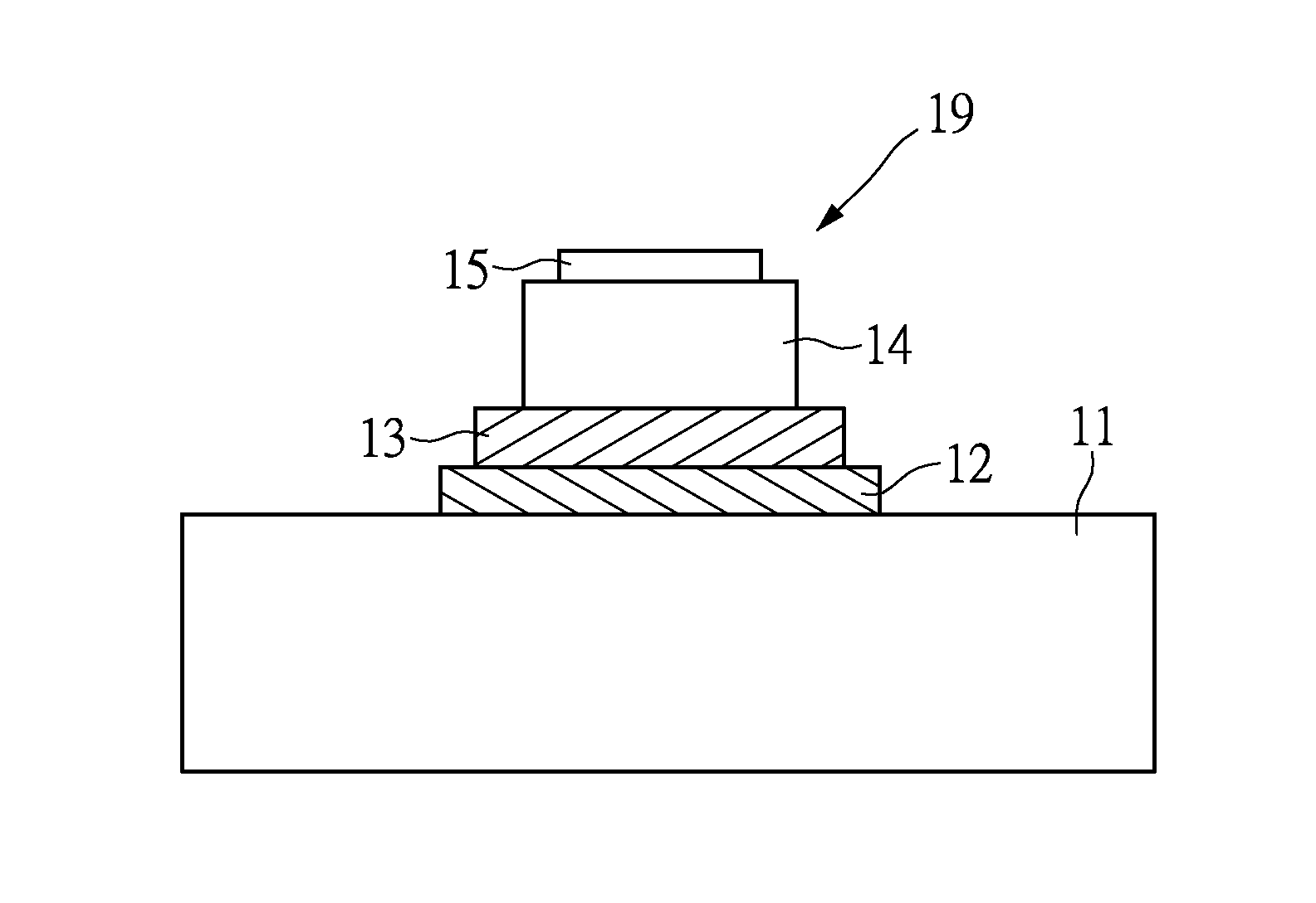
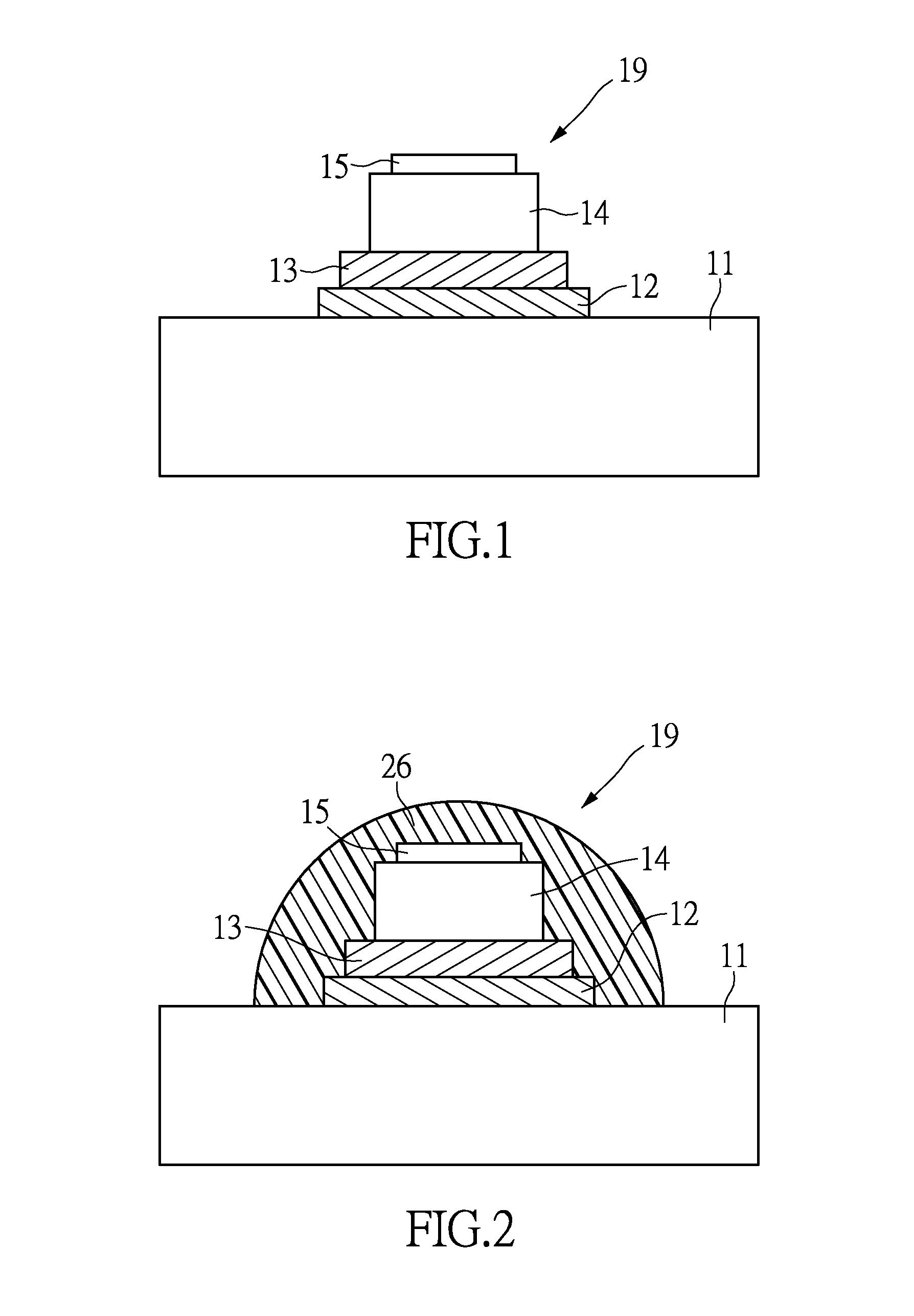
[0020]Please refer to FIG. 1 as a sectional drawing of an electrode structure in accordance with first embodiment of the instant disclosure. In this embodiment, the electrode structure of the instant disclosure comprises a flexible substrate 11 and a plurality of electrode lines 19 (only one line illustrated in FIG. 1), and in practice, the electrode lines 19 can be set on the flexible substrate 11 in parallel. Wherein the electrode lines 19 includes a first adhesive layer 12 set on the flexible substrate 11, a second adhesive layer 13 set on the first adhesive layer 12, a conductive layer 14 set on the second adhesive layer 13 and a first resist layer 15 set on the conductive layer 14.

[0021]In detail, the first adhesive layer 12 covers on the flexible substrate 11 to improve the adhesion to the flexible substrate 11 and with the effect of anti-reflective, anti-interference, anti-rainbow pattern, anti-abrasion, anti-scratch and enhance the comfort to human eyes. The second adhesive ...

second embodiment

[0030]FIG. 2 is a sectional drawing of an electrode structure in accordance with second embodiment of the instant disclosure. In the instant disclosure, the electrode lines 19 may further comprise a second resist layer 26 set on the first resist layer 15 and at least cover the side of the conductive layer 14, if need be, the electrode lines 19 can entirely cover the first resist layer 15, the conductive layer 14, the second adhesive layer 13 and the first adhesive layer 12 on the flexible substrate 11. The second resist layer 26 covers the first resist layer 15 to improve the corrosion resistance of the conductive layer 14, to reduce the chance of foreign body rubbing metal electrodes to damage and lower the front and side reflective of metal electrodes.

[0031]In the instant disclosure, the material to form the second resist layer 26 may comprise one of the groups consisting of oxide, polymer, carbon and its complex. The oxide may comprise silicon oxide, titanium oxide, aluminum oxid...


PUM


Abstract

An electrode structure for a touchscreen is provided. The electrode structure includes a flexible substrate and a plurality of electrode lines, wherein the electrode line includes a first adhesive layer, a second adhesive layer, a conductive layer, a first resist layer and a second resist layer. Through the configuration above, the electrode structure of the present application adheres the flexible substrate strongly by the first adhesive layer, and the second adhesive layer strengthen the adhesion between the first adhesive layer and the conductive layer, so that the conductive layer may be firmly adhered to the flexible substrate, even change the shape of the substrate, the electrode lines are not easy to fall off. The present invention also provides an electrode structure for scattering the reflective metallic luster to make observer imperceptible and reduce the backlight interference.

Description

BACKGROUND OF THE INVENTION[0001]1. Field of the Invention[0002]The instant disclosure relates to an electrode structure for touchscreen; in particular, to an electrode structure for a flexible touch panel.[0003]2. Description of Related Art[0004]Conventional touch panel generally use indium tin oxide (ITO) to form the electrodes to make the electrodes imperceptible. However, with the gradual development to the large-size touch panel, some defects of ITO electrodes are emerged such as high resistance, slow response and etc. Therefore, the industry has been trying to use thin metal wires to form the electrodes.[0005]In general, the touch panel using metal conductor as the electrodes often occurs the electrodes peeling due to the bad adhesion between the metal conductor and the common substrate, thereby affecting the performance of the touch panel. If applied to the flexible touch panel, it will exacerbate the occurrence of electrode peeling because the substrate is frequently deforme...

Claims


Application Information

Patent Timeline
Patent Type & Authority Patents(United States)
IPC IPC(8): H05K3/38H05K1/02H05K1/03G06F3/041
CPCG06F3/041H05K3/386H05K3/388G06F3/044H05K1/0274H05K1/0393H05K2201/0329H05K2201/0338G06F2203/04102G06F2203/04103G06F3/0446G06F3/0445
Inventor YEH, YU-CHOUYEH, TSUNG-HERLIAO, SZU-KAITSUI, CHIU-CHENG
Owner J TOUCH CORPORATION
Learn More