Angiographic image acquisition system and method with automatic shutter adaptation for yielding a reduced field of view covering a segmented target structure or lesion for decreasing X-radiation dose in minimally invasive X-ray-guided interventions

an image acquisition system and automatic shutter technology, applied in angiography, angiography, diaphragm/collimeter handling, etc., can solve the problems of reducing affecting the image quality of the obtained image, and the most difficult imaging task in the cardiac catheterization lab is imaging patients at steep viewing angles. achieve the effect of reducing the radiation dos

Active Publication Date: 2016-03-08
KONINKLIJKE PHILIPS ELECTRONICS NV
View PDF21 Cites 27 Cited by
  • Summary
  • Abstract
  • Description
  • Claims
  • Application Information

AI Technical Summary

Benefits of technology

[0023]It may thus be an object of the present invention to describe an image acquisition device and method which helps to decrease the radiation dose required in the scope of minimally invasive image-guided interventions that are carried out based on a previously reconstructed virtual 3D representation of an anatomical object of interest (such as e.g. a vessel segment of a patient's cardiovascular system), a pathological target structure (e.g. a stenosis, an aneurysm, etc.) to be treated or any type of lesion to which an intervention device (such as e.g. a catheter brought into a patient's cardiovascular system) or implant (e.g. an angioplastic stent to be implanted during an intracoronary stent implantation procedure) has to be navigated.
[0024]To achieve this object, a first exemplary embodiment of the present invention is directed to an angiographic image acquisition method for acquiring and recording a set of image data used for three-dimensionally reconstructing a target structure or lesion in a region of interest of a patient's cardiovascular system to be graphically visualized, thereby yielding a virtual 3D representation of an artery tree's vessel segments located within said region of interest with said 3D representation being calculated and reconstructed such that said vessel segments are shown from the perspective of an optimal viewing angle yielding minimum perspective foreshortening and minimum vessel overlap. According to the present invention, said method comprises the steps of subjecting the image data set of the 3D representation associated with the precalculated optimal viewing angle to a 3D segmentation algorithm in order to find the contours of the target structure or lesion to be examined and interventionally treated within said region of interest and automatically adjusting a collimator wedge position and / or aperture of a shutter mechanism used for collimating an X-ray beam emitted by an X-ray source (such as e.g. an X-ray source of an interventional X-ray imaging system which can e.g. be C-arm based) to which said patient is exposed during an image-guided radiographic examination procedure based on data obtained as a result of said segmentation which indicate the contour and size of said target structure or lesion. The aim is to reduce the region of interest to a field of view that covers said target structure or lesion together with a user-definable portion of the surrounding vasculature.
[0028]A second exemplary embodiment of the present invention is dedicated to an angiographic image acquisition method for determining, based on a sequence of virtual 3D representations for tracking a segmented target structure or lesion in a region of interest of a patient's cardiovascular system to be graphically visualized over the time, the optimal projection direction of this target structure or lesion with respect to overlap and perspective foreshortening for each of these 3D representations. It may thereby be provided that each 3D representation is generated by straightforward 3D reconstruction of an image data set that is being acquired in a 3DRA-based image acquisition session carried out during a minimally invasive image-guided intervention procedure for interventionally treating said target structure or lesion. According to this embodiment, said method thereby comprises the step of automatically adjusting a collimator wedge position and / or aperture of a shutter mechanism used for collimating an X-ray beam emitted by an X-ray source to which said patient is exposed during an image-guided radiographic examination procedure based on data obtained as a result of a dynamically updated segmentation which indicate the contour and size of the target structure or lesion so as to reduce the region of interest to a field of view that covers said target structure or lesion together with a user-definable portion of the surrounding vasculature, wherein said field of view is continually resized dependent on the dynamically updated segmentation.

Problems solved by technology

However, current systems still exhibit high radiation exposure.
The key problems thereby relate to imaging, radiation hazards and operational issues.
One of the most difficult imaging tasks in the cardiac catheterization lab is imaging patients at steep viewing angles.
With conventional systems, a large-area detector close to the patient causes more scattered radiation reaching the detector than image radiation, which thus may severely degrade the obtained image quality.
Another serious problem consists in the fact that overlying anatomy may inhibit viewing and navigation.
Discerning 3-D anatomy from these flat images is difficult.
In addition, image clutter and shadowing of the heart by ribs or the spine often degrades image clarity.
A further problem conventional X-ray based cardiac catheterization systems are typically faced with is exposing both the patient and the interventionalist to a significant amount of radiation.
Prolonged exposure can cause radiation skin burns on patients and increase the risk of cancer to the interventionalists and catheterization lab staff.
In cardiac X-ray images, on the other hand, specific high-density anatomical structures (such as e.g. the spine, specific vertebras, etc.) or foreign objects (such as e.g. pacemaker leads and surgical stitches, etc.) are most of the time visible in the X-ray image and may thus at least partly obstruct or jeopardize the visibility, detection and / or tracking of interventional tools, either because they create similar patterns or because they cast a shadow on the objects which shall be detected.
Classical image subtraction techniques do not help in case of slowly moving interventional tools and would require new acquisitions of reference sequences every time the 2D view changes.
However, due to the problem of vessel overlap and perspective foreshortening, multiple projections are necessary to adequately reconstruct the coronary arterial tree with arteriography.
Aside therefrom, the overlap measurement is limiting because it is performed based on the single stenotic segment with only immediate adjacent vessels.
Sub-optimal solutions in determining optimal view are ineffective when the segment is more complex and more distal vessels were overlapped, both conditions of which are common in clinical conditions.

Method used


Image

  • Angiographic image acquisition system and method with automatic shutter adaptation for yielding a reduced field of view covering a segmented target structure or lesion for decreasing X-radiation dose in minimally invasive X-ray-guided interventions
  • Angiographic image acquisition system and method with automatic shutter adaptation for yielding a reduced field of view covering a segmented target structure or lesion for decreasing X-radiation dose in minimally invasive X-ray-guided interventions
  • Angiographic image acquisition system and method with automatic shutter adaptation for yielding a reduced field of view covering a segmented target structure or lesion for decreasing X-radiation dose in minimally invasive X-ray-guided interventions

Examples


Embodiment Construction

[0041]In the following, the proposed image acquisition device and method according to the present invention will be explained in more detail with respect to special refinements and referring to the accompanying drawings.

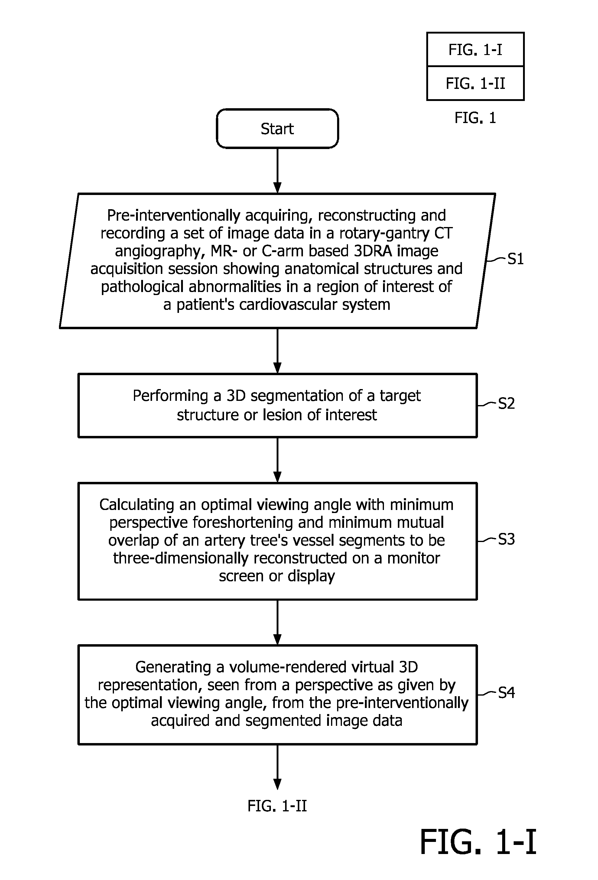
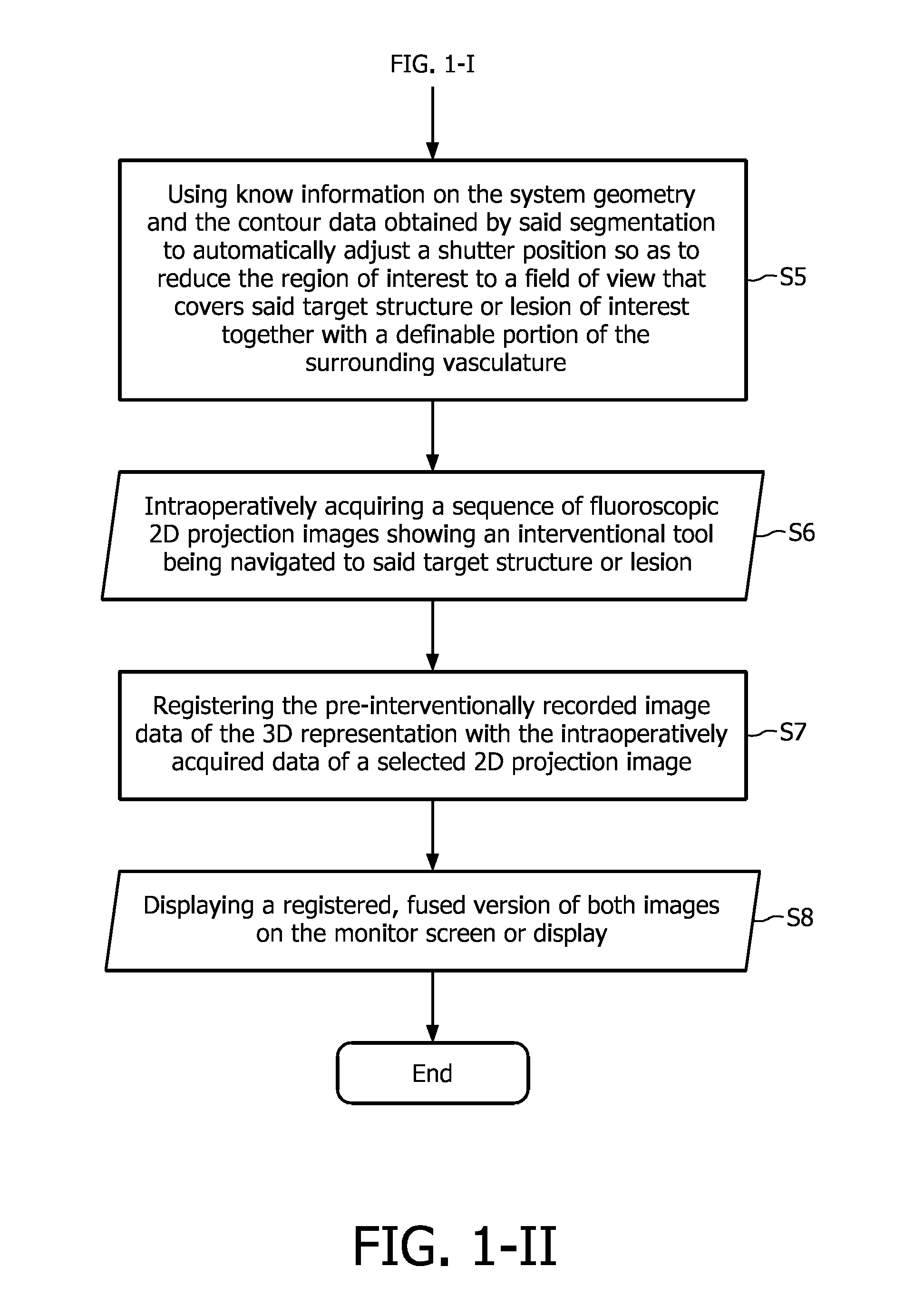
[0042]The flowchart depicted in FIG. 1 illustrates the proposed image acquisition method according to the above-described first exemplary embodiment of the present invention. The proposed method begins with the step of pre-interventionally acquiring, reconstructing and recording (S1) a set of image data in a rotary-gantry based CT angiography imaging, MR- or C-arm based 3DRA image acquisition session, said image data showing anatomical structures and / or pathological abnormalities in a region of interest of a patient's cardiovascular system to be examined and treated by executing a minimally invasive image-guided intervention. These image data are then subjected to a 3D segmentation algorithm (S2) in order to find the contours and, optionally, calculate the size of a ...


PUM


Abstract

The present invention refers to an angiographic image acquisition system and method which can beneficially be used in the scope of minimally invasive image-guided interventions. In particular, the present invention relates to a system and method for graphically visualizing a pre-interventionally virtual 3D representation of a patient's coronary artery tree's vessel segments in a region of interest of a patient's cardiovascular system to be three-dimensionally reconstructed. Optionally, this 3D representation can then be fused with an intraoperatively acquired fluoroscopic 2D live image of an interventional tool. According to the present invention, said method comprises the steps of subjecting the image data set of the 3D representation associated with the precalculated optimal viewing angle to a 3D segmentation algorithm (S4) in order to find the contours of a target structure or lesion to be examined and interventionally treated within a region of interest and automatically adjusting (S5) a collimator wedge position and / or aperture of a shutter mechanism used for collimating an X-ray beam emitted by an X-ray source of a C-arm-based 3D rotational angiography device or rotational gantry-based CT imaging system to which the patient is exposed during an image-guided radiographic examination procedure based on data obtained as a result of said segmentation which indicate the contour and size of said target structure or lesion. The aim is to reduce the region of interest to a field of view that covers said target structure or lesion together with a user-definable portion of the surrounding vasculature.

Description

[0001]The present invention refers to an angiographic image acquisition system and method which can beneficially be used in the scope of minimally invasive image-guided interventions where image data showing an interventional tool while being navigated through a patient's cardiovascular and / or cardiac anatomy are intraoperatively acquired based on three-dimensional imaging and a set of image data for three-dimensionally reconstructing this anatomy are pre-interventionally acquired by means of MR, CT, C-arm-based 3DRA or any other imaging modality. In particular, the present invention relates to a system and method for graphically visualizing a pre-interventionally generated 3D representation of a patient's coronary artery tree's vessel segments in a region of interest of a patient's cardiovascular system to be three-dimensionally reconstructed, wherein said image acquisition is carried out by means of a conventional magnet resonance imaging system, a C-arm-based 3D rotational angiog...

Claims


Application Information

Patent Timeline
Patent Type & Authority Patents(United States)
IPC IPC(8): G06F19/00G06T11/00G06T15/08A61B6/00A61B6/06
CPCG06T11/008A61B6/06A61B6/4441A61B6/481A61B6/504A61B6/5247A61B6/542G06F19/321G06T15/08G06F19/3406G06T2211/404G16H30/20G16H40/63
Inventor GRASS, MICHAELSCHAEFER, DIRKSCHOONENBERG, GERT ANTONIUS FRANCISCUS
Owner KONINKLIJKE PHILIPS ELECTRONICS NV
Why Eureka
Try Eureka