
Device for supplying energy to hydraulically or pneumatically actuated active implants

a technology of active implants and hydraulic actuators, which is applied in the direction of prosthesis, other medical devices, and other directions, can solve the problems of affecting the comfort of wear of patients, increasing the risk of pocket infections, and increasing the number of components implanted, so as to achieve prompt availability of energy and optimal damping of the system

Active Publication Date: 2016-03-15
DEUTSCHES ZENTRUM FUER LUFT & RAUMFAHRT EV
View PDF11 Cites 0 Cited by
  • Summary
  • Abstract
  • Description
  • Claims
  • Application Information

AI Technical Summary

Benefits of technology

This patent describes a device that allows for easier implantation in patients and decreases the risk of infection. The device includes a compensation container, receiving coil, and possibly an electric line all in a single pocket in the patient's body. The pocket is made rigid or flexible to adapt to the patient's movements and body. This design allows for better ingrowth in the patient and can contain the pressure buildup caused by the expansion of the compensation container without affecting the housing.

Problems solved by technology

In practice, the number of components implanted substantially increases the risk of pocket infections.
Moreover, the surgery and the sterilization are more time-consuming.
Further, the comfort of wear for the patient is affected negatively.
Therefore, implantability may no longer be an option with small persons, such as children.
These bear an increased risk of pocket infections and are often perceived by patients as disturbing.
Further, the risk of a pocket infection decreases and the comfort of wear for the patient is increased.

Method used


Image

  • Device for supplying energy to hydraulically or pneumatically actuated active implants
  • Device for supplying energy to hydraulically or pneumatically actuated active implants
  • Device for supplying energy to hydraulically or pneumatically actuated active implants

Examples


Embodiment Construction

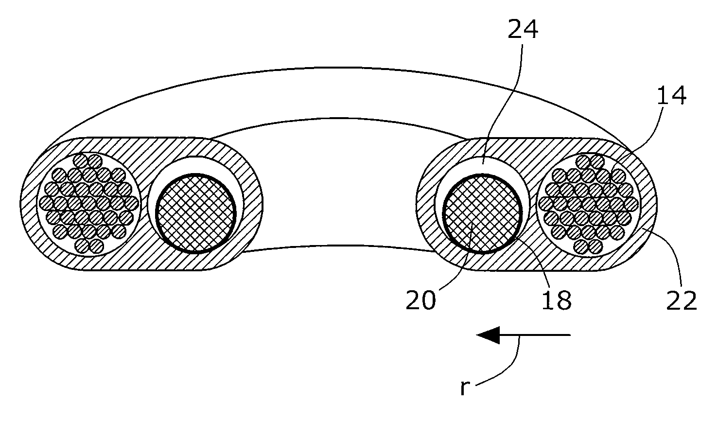
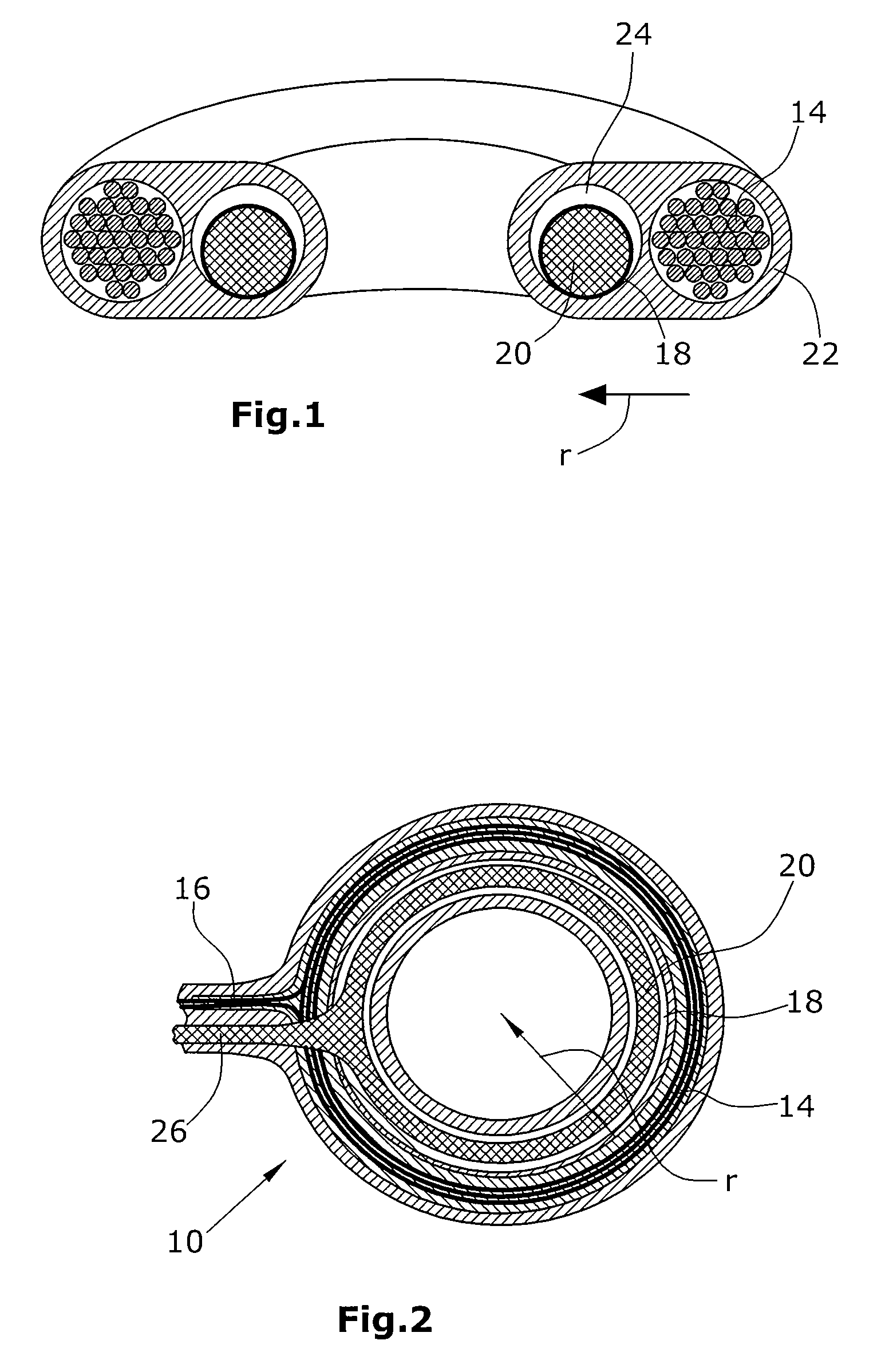
[0044]FIG. 1 shows the receiving coil 14 in section. The latter is arranged within the incompressible housing 22 which is toroidal in shape. The compensation container 18, which receives the transmitter fluid 20, extends in the radial direction inside the receiving coil 14. The medium 24 for adjusting the compliance of the outer wall of the compensation container 18 is arranged in the cavity between the outer wall of the compensation container 18 and the inner wall of the incompressible chamber 22. The same can be supplied to or withdrawn from the incompressible housing 22 via a non-illustrated port.

[0045]In addition to the components mentioned, FIG. 2 illustrates the electrical line 16 to the implant 12. Further, the fluid line 26 is shown via which the transmitter fluid 20 can be conveyed from the compensation container 18 to the active implant 12 and back. Here, conveying is effected by means of a non-illustrated pump which may have an electric drive, for instance.

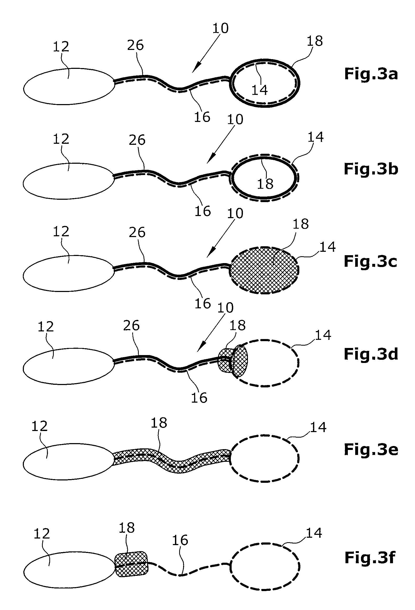
[0046]In FIGS. ...


PUM


Abstract

A device for supplying energy to hydraulically or pneumatically actuated active implants. The device can take the form of pumping systems, metering systems, and / or occlusion systems. The device comprises a receiving coil for generating an electric voltage due to a changing magnetic flux that is generated by an extracorporeal transmitting coil. The receiving coil is designed such that said coil can be implanted into subcutaneous tissue. Furthermore, an electric line is provided for transmitting the electric current that is generated by the receiving coil from the receiving coil to the active implant. The device further comprises a compensation container for temporarily receiving a transmitter fluid, by means of which the active implant is activated. The compensating container is mounted on the receiving coil and / or on the electric line such that the compensating container together with the receiving coil and / or the electric line can be implanted into a common tissue or muscle pocket in the body of a patient.

Description

BACKGROUND[0001]1. Field of the Disclosure[0002]The disclosure refers to a device for supplying energy to hydraulically or pneumatically actuated active implants.[0003]2. Discussion of the Background Art[0004]These may be pumping systems such as artificial hearts or cardiac assist systems (ventricular assist devices), metering systems (such as drug pumps for pain therapy) or occlusion systems (sphincters).[0005]Ideally, such active implants should be configured so as to be fully implantable so that it becomes unnecessary to provide percutaneous energy lines for the supply of energy. One possible way of supplying energy is to supply current to the implant in a wireless manner via an inductive energy transmission unit. Here, implantable coils are used to transmit energy to the target implant, which implantable coils are most frequently implanted in the subcutaneous tissue of the abdominal section or the pectoral muscle area. Such an arrangement for wireless energy transmission is desc...

Claims


Application Information

Patent Timeline
Patent Type & Authority Patents(United States)
IPC IPC(8): A61M1/12A61M1/10A61M5/145A61M5/142A61F2/00A61N1/378
CPCA61M1/127A61M1/1037A61M1/1044A61M1/122A61F2/0036A61M5/14276A61M2005/14513A61M2205/8243A61N1/3787A61M60/405A61M60/869A61M60/148A61M60/427A61M60/878A61M60/268A61M60/196A61M60/873
Inventor SCHMID, THOMASVODERMAYER, BERNHARDRIECKE, CORNELIARYBAK, ANNIKAGRZESKI, MATTHIAS
Owner DEUTSCHES ZENTRUM FUER LUFT & RAUMFAHRT EV
Learn More