Structure and method of bonding copper and aluminum

a technology of copper and aluminum, applied in the direction of solventing apparatus, manufacturing tools, transportation and packaging, etc., can solve the problems of difficult to achieve, hard and brittle intermetallics of liquid mixture of aluminum and copper, and the formation of hard and brittle intermetallics

Active Publication Date: 2016-03-22
GM GLOBAL TECH OPERATIONS LLC +1
View PDF14 Cites 2 Cited by
  • Summary
  • Abstract
  • Description
  • Claims
  • Application Information

AI Technical Summary

Benefits of technology

[0004]A method of bonding a first metallic workpiece to a second metallic workpiece, where the two workpieces are made of materials having different melting points and thermal conductivities, is provided. The materials of the first metallic workpiece and the second metallic workpiece may be copper and aluminum, respectively. The method allows the two workpieces to be bonded without the creation of intermetallics between the two workpieces.
[0008]A bonded structure of copper and aluminum is also provided. The bonded structure may be formed by the method above. The bonded structure includes a first metallic workpiece made of copper, and a second metallic workpiece made of aluminum. The first metallic workpiece has a first coating applied to at least a portion of the first metallic workpiece. The material of the first coating generally has a lower melting point than copper, and may include, but is not limited to, zinc. The first metallic workpiece may further have an optional second coating between the first metallic workpiece and the first coating. The material of the second coating generally has a higher melting point than copper, and may include, but is not limited to, nickel. The second coating ensures that there is minimal diffusion of the first coating into the first metallic workpiece.

Problems solved by technology

However, this is known to be difficult to accomplish due to the differing melting points and thermal conductivities of aluminum and copper.
In addition, a liquid mixture of aluminum and copper forms hard and brittle intermetallics as it solidifies and cools.

Method used


Image

  • Structure and method of bonding copper and aluminum
  • Structure and method of bonding copper and aluminum
  • Structure and method of bonding copper and aluminum

Examples


Embodiment Construction

[0018]Those having ordinary skill in the art will recognize that terms such as “above,”“below,”“upward,”“downward,” et cetera, are used descriptively of the figures, and do not represent limitations on the scope of the invention, as defined by the appended claims. Any numerical designations, such as “first” or “second” are illustrative only and are not intended to limit the scope of the invention in any way.

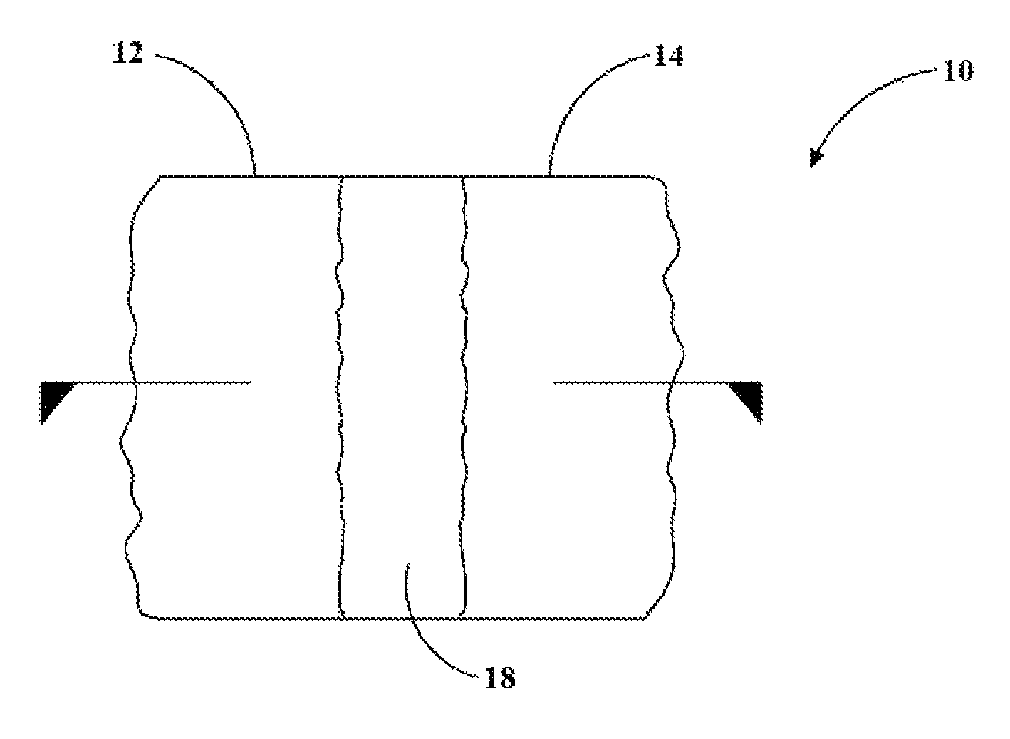
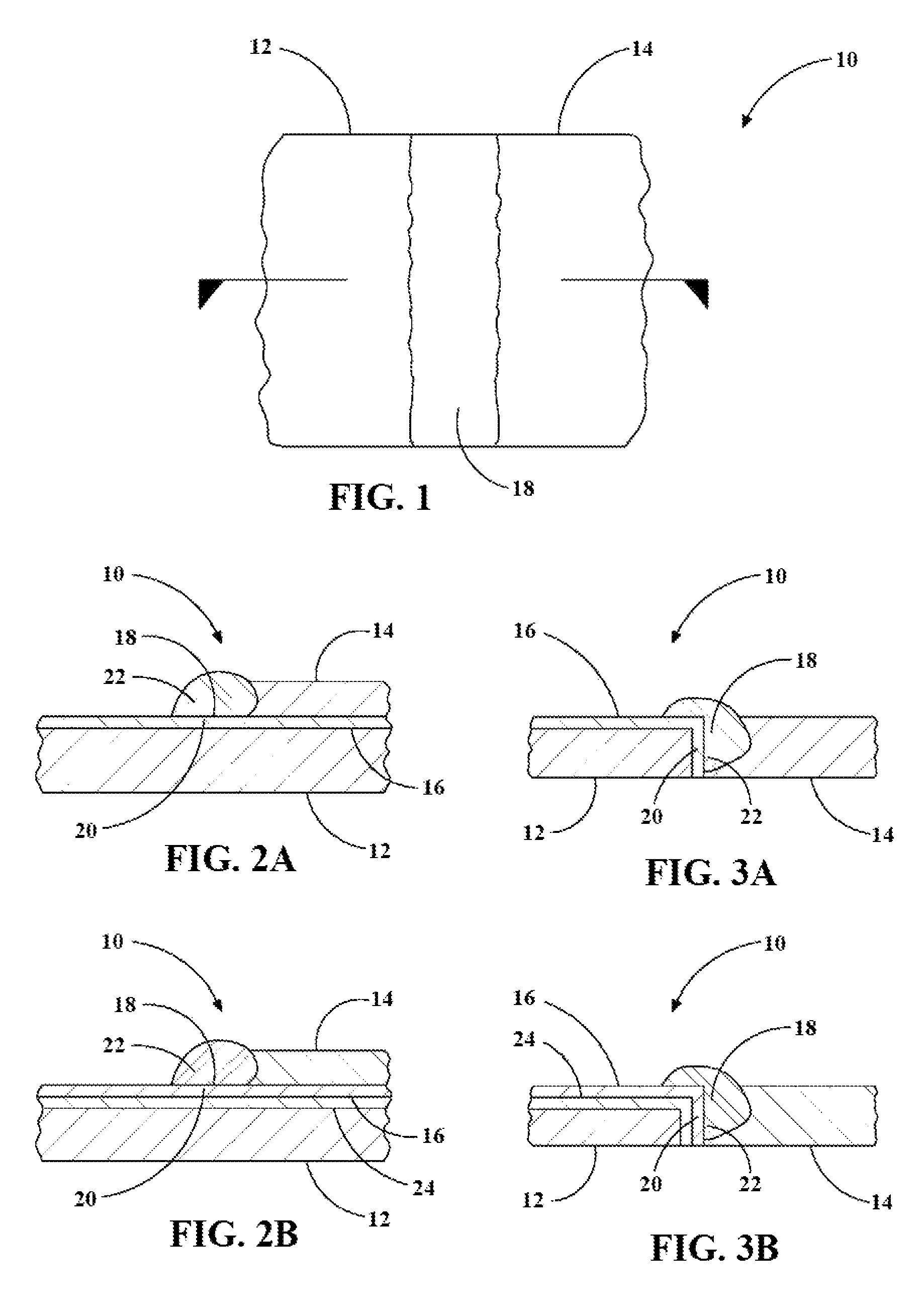
[0019]Referring to the drawings, wherein like reference numbers correspond to like or similar components wherever possible throughout the several figures, a bonded structure 10 is shown in FIG. 1. The bonded structure 10 includes a first metallic workpiece made of copper (hereinafter, copper workpiece 12) and a second metallic workpiece made of aluminum (hereinafter, aluminum workpiece 14). While the first metallic workpiece and the second metallic workpiece are described as a copper workpiece 12 and an aluminum workpiece 14, respectfully, it should be appreciated that they may b...


PUM

PropertyMeasurementUnit
melting pointsaaaaaaaaaa
thermal conductivitiesaaaaaaaaaa
melting pointaaaaaaaaaa

Abstract

A bonded structure of aluminum and copper is formed by bonding a copper workpiece and an aluminum workpiece together along a joint via an arc welding process. The copper workpiece has a first coating, having a lower melting point than copper, applied to at least a portion of it. The first coating allows the copper workpiece to be wetted and brazed, while the aluminum workpiece is melted and fused along the joint. The arc welding process involves the cyclic alternating of a first stage, in which an electric current is supplied to a welding wire as it is moved toward the workpieces, and a second stage, in which the electric current is reduced and the welding wire is moved away from the workpieces, to generate and detach a plurality of molten droplets along the joint. Each molten droplet is formed from the welding wire in the first stage.

Description

STATEMENT REGARDING FEDERALLY SPONSORED RESEARCH OR DEVELOPMENT[0001]This invention was made with U.S. Government support under an Agreement / Project Z264-DPN and Z411-DPN. The U.S. government may have certain rights in this invention.TECHNICAL FIELD[0002]The present invention relates to a bonded structure of copper and aluminum, and a method of bonding a copper workpiece and an aluminum workpiece together to form the bonded structure.BACKGROUND[0003]Aluminum and copper are two of the most widely used conductor materials due to their high conductivity and relatively low cost. As such, it is often desired to join, such as by welding, copper components and aluminum components to each other to be part of an electric circuit in various applications, such as in hybrid electrical vehicles. However, this is known to be difficult to accomplish due to the differing melting points and thermal conductivities of aluminum and copper. In addition, a liquid mixture of aluminum and copper forms hard...

Claims


Application Information

Patent Timeline
Patent Type & Authority Patents(United States)
IPC IPC(8): B23K9/00B32B15/01B23K35/30B23K33/00B32B15/10B23K35/365B23K9/23B23K9/235B23K35/28
CPCB23K9/0008B23K9/232B23K9/235B23K35/286B23K35/302B23K35/365B32B15/01B32B15/017B23K2203/10B23K2203/12Y10T428/12736B23K1/19B23K35/001B23K2103/12B23K2103/10
Inventor CHEN, CHIH-CHANGSIMONE, COREY
Owner GM GLOBAL TECH OPERATIONS LLC
Why Eureka
Try Eureka