
Modular honing guide system

a honing guide and module technology, applied in the field of modules, can solve the problems of limiting the user's choice of honing stone sizes, unrestricted random motion of the tool edge, and unrestricted access to the entire surface area of the abrading medium,

Active Publication Date: 2016-03-22
SABO DANIEL B
View PDF38 Cites 19 Cited by
  • Summary
  • Abstract
  • Description
  • Claims
  • Application Information

AI Technical Summary

Benefits of technology

This patent describes a system and method for sharpening and honing different types of edge-tools using a modular member-interchangeable system. The system includes a base and tool holder and can be used with different tool types, such as V- tools or fingernail profiles. The system allows for easy interchange of components and ensures consistent and repeatable results. The technical effects include versatility, expandability, and ease of use for different types of edge-tools.

Problems solved by technology

A number of problems with these types of honing guides result when an abrading surface is used as a support base for a jig.
With this type of a jig, a tool edge is un able to access the entire surface area of an abrading medium with unrestricted random motion.
This limits a users choices as to sizes of honing stones that can be used with these types of jigs.
Smaller honing stones that a user owns are not useable with these types of honing guides.
Since some areas of an abrading surface are not accessible to a tool edge, un even wear of a honing stone or abrading surface can result.
And since an abrading surface is used as a support base, with long term use, such can cause un wanted wear to a jig.
This design however still requires a significant portion of the surface area of the stone to support the honing guide.
Although a honing stone can be rotated 180° so that both lengthwise edges of the honing stone can have access to a tool edge, a problem still remains for edge tools honed at low bevel angles on narrow stones.
Thus, although the side to side motion, which does have merit with the idea of providing greater access to the surface area of larger stones compared to the then prior art—the problem of providing greater access to the honing stone is still not solved for tools requiring low bevel angles on relatively narrow honing stones.
For some of the narrower honing stones, a tool edge will not be able to reach the edge of the honing stone, since the stone is acting as a support base for the jig.
Another problem that this embodiment brings about, is if the user tends to hone many tools at low bevel angles; depending on the width of the honing stone, only the areas near the edges of a honing stone will come into contact with a tool edge.
Although these types of jigs offer an entire surface area of an abrading surface to a tool edge, a problem the applicant has found with these types of honing guides, is that when a honing stone of a different thickness is swapped in, bevel and skew angles at a tool edge change due to an abrading height differential.
Base height adjustability was in the original design; however, the Crocker solution does not address the problem of raising the base height of the jig perpendicular or normal to the work surface by the exact amount of a height differential between two abrading surfaces independent of any bevel and skew angle a tool is set.
Thus, when adjusting the correct bevel angle for one abrading surface, it is not possible to maintain that angle when switching to another abrading surface of a differing thickness.
This causes additional honing time as well as un necessary tool wear, and thus shorter tool life.
For this very reason, many of the honing guides on the market today for wider tool shanks have been designed such that a base of the honing guide rides on the abrading surface due to the difficulty in creating a system for vertical base height adjustability independent of bevel and skew angle settings.
The applicant has found it difficult to hone short shafted, tiny hand carving gouges used in the wood cut print making arts, such as Japanese style hand carving gouges, to a consistent edge.
Tiny western style gouges used in fine detail work are also a challenge to hone a tool edge to a uniform profile.
The prior art is lacking in a universal manual honing solution that can be used on small planar abrasive surfaces, that can be applied to these tiny gouges, to larger gouges and to wide flat shanked cutting edges such as plane blades.
This is because it is difficult to find a solution to clamp short tool shanks and present them to an abrading surface at a low bevel angle without a honing guide base bumping in to the edge of a honing stone.
As these smaller tools become shorter with use, it is difficult to hone a uniform edge profile due to less shank length to either hold on to, or clamp into a honing guide.
However, the design requires that a work surface which supports the jig base, be coplanar with the abrading surface at all times. This design does not allow for quick and easy adjustment of the jig base.
Unless one has the equipment such as a power planer to fabricate several work surfaces of differing thickness, or the manual skills to fashion several work surfaces of uniform thickness using hand planes, the jig base will be unable to maintain consistent bevel and skew angles without repeated re adjustment each time a new abrading surface is swapped in.
Although wet grinding systems are capable of honing a wide variety of tools, such requires expensive motorized equipment and grinding wheels or abrasive discs.
The user is thus limited to a narrow range of grinding wheels which operate on motorized equipment, and is unable to fully utilize the diverse and wide ranging types of honing stones and abrasive papers or films available to the consumer today.

Method used


Image

  • Modular honing guide system
  • Modular honing guide system
  • Modular honing guide system

Examples


first embodiment

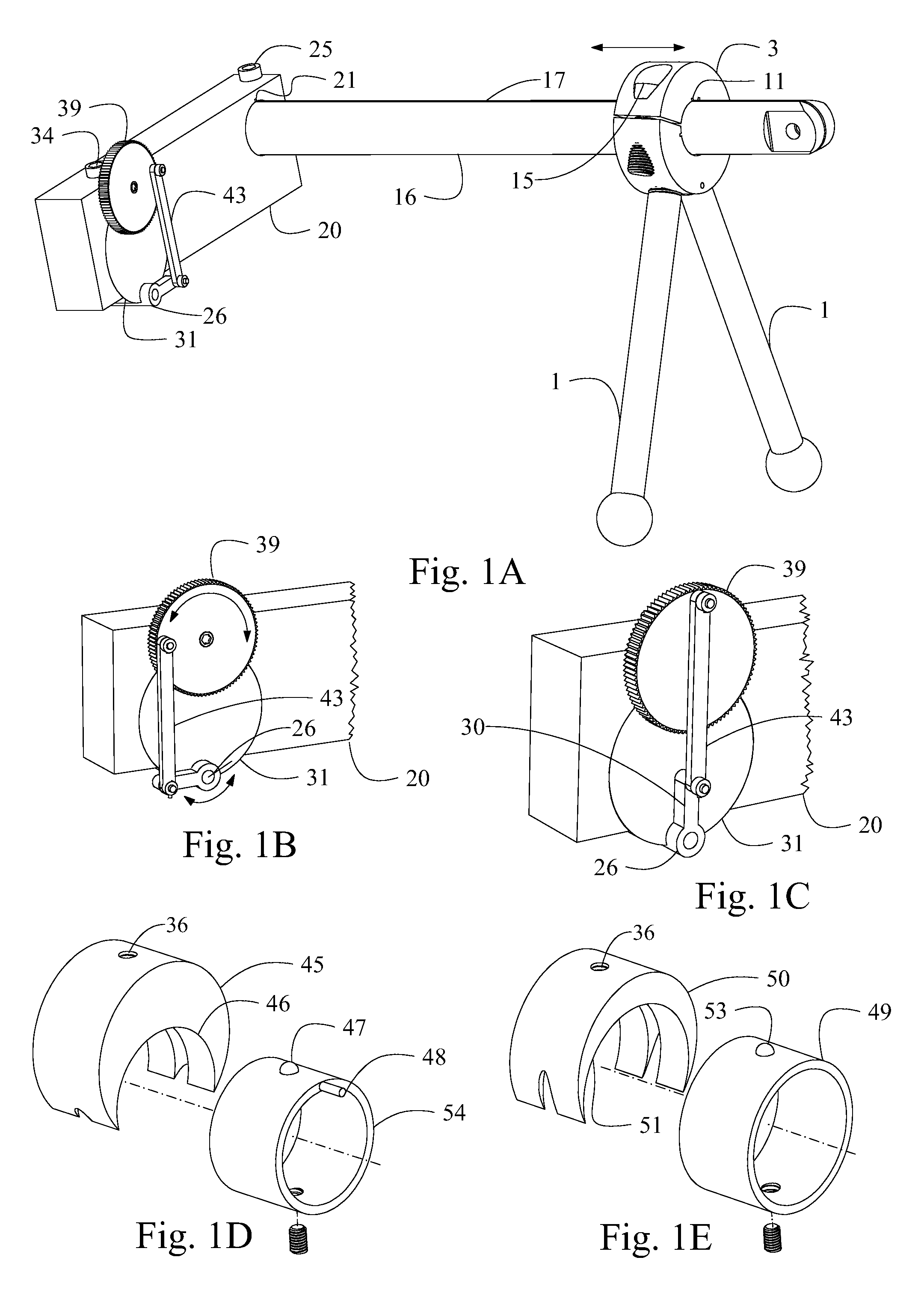
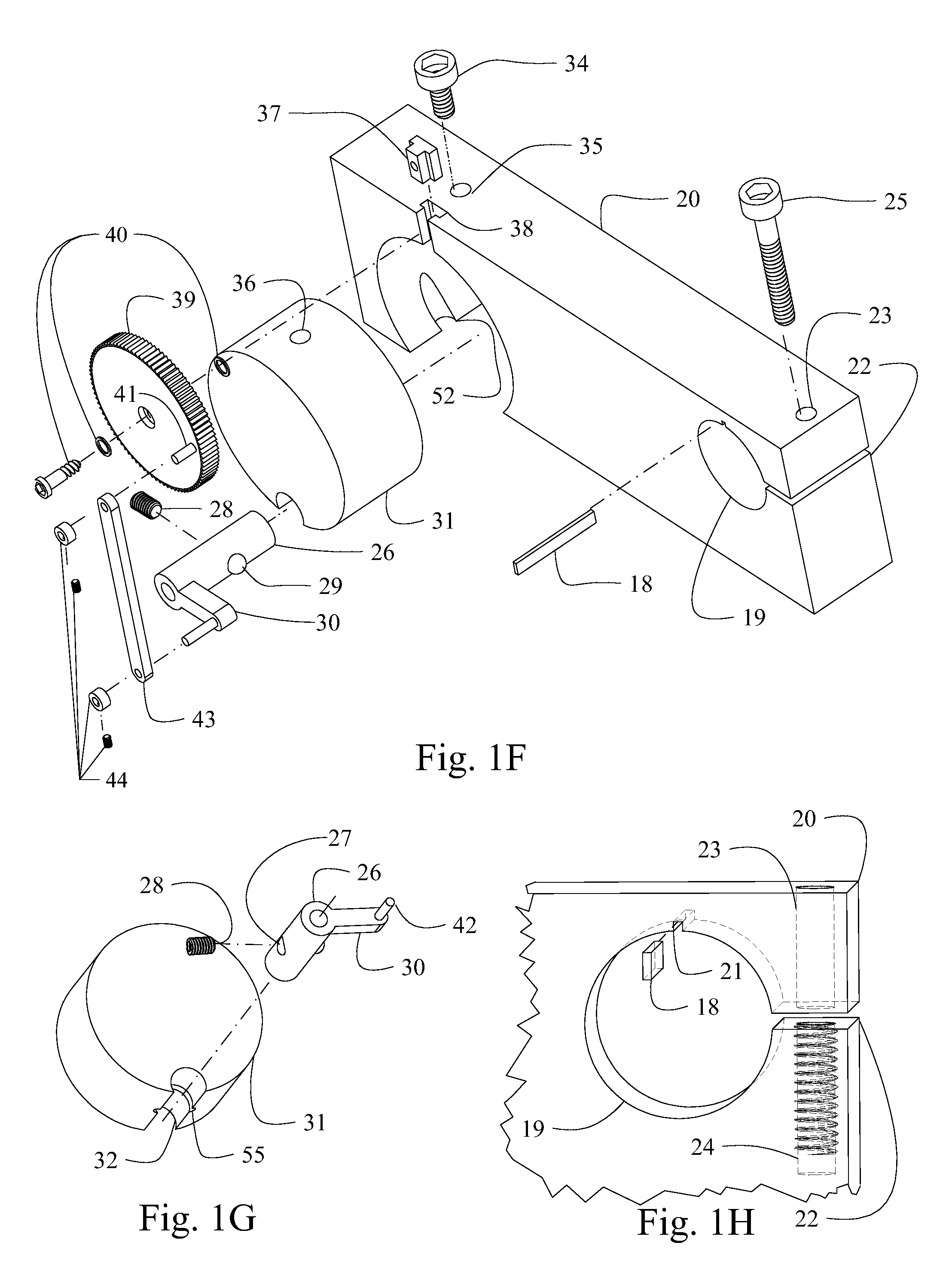
[0049]Due to a honing guide system in which a plurality of members are used in all honing and sharpening applications and configurations, all drawing Figs. with number prefixes between 1 and 18 are considered the First Embodiment of this specification. Drawing Figs. starting with the number 19 and 20 prefixes are alternative embodiments of the members.

[0050]All described members, except fasteners, can be manufactured of (and not limited to) aluminum, steel or other metallic materials, or from plastics or composite materials or wood.

FIGS. 1A Through 1P

Detailed Static Description

[0051]FIGS. 1A and 1O show an assembled honing guide configuration for out cannel gouges. An embodiment of a member of the configuration, leg 1 (FIGS. 1A, 1N, 1O), is an elongated support base member with a spherical or hemispherical shaped end or ball 6 (FIG. 1N), and a threaded end 2 (FIG. 1N). At present, it is anticipated that the spherical end could preferably be made of a hardened material able to resist...


PUM

PropertyMeasurementUnit
Electric chargeaaaaaaaaaa
Currentaaaaaaaaaa
Currentaaaaaaaaaa

Abstract

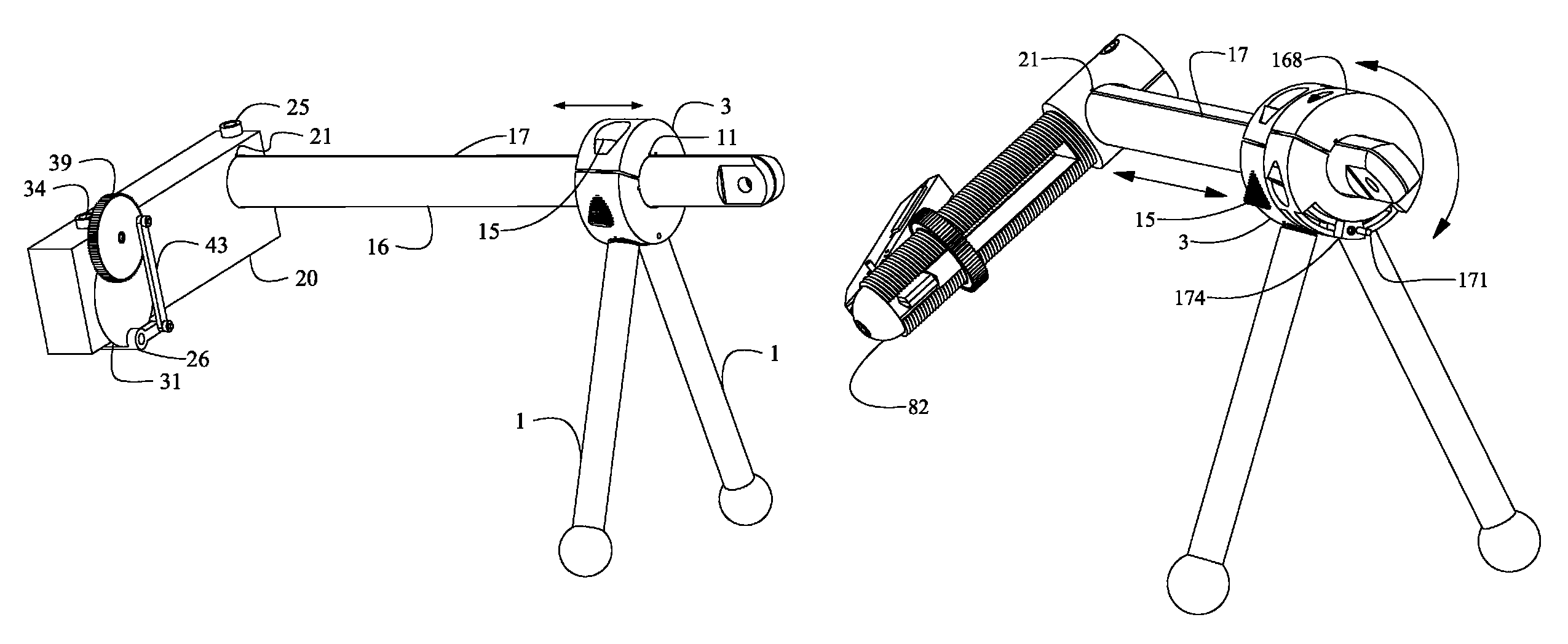
A modular honing guide system comprised of interchangeable parts, having a multitude of configurations (FIGS. 1A, 4C, 8A, 9A, 10P, 11D, 12H, 13A, 14A, 16A, 17A) for manually sharpening or honing a multitude of tool types used for but not limited to wood carving, wood working, fine art printmaking, jewelry making and metal work. Tools are honed on a planar abrasive surface, while a honing guide base is moved across a supporting work surface. A plurality of edge tool clamps can be mounted to a unified honing guide base system. With manual random motion or combined random motion and uniform rotational or rocking motion, a combined cutting edge and honing guide is moved across abrading and work surfaces respectively. A multitude of bevel, skew and cutting edge profiles are attained. System is an improvement over honing guides which are designed for specific or limited types of edge tools.

Description

CROSS-REFERENCE TO RELATED APPLICATIONS[0001]This application claims the benefit of provisional patent application Ser. No. 61 / 687,910, filed May 3, 2012 by the present inventor, which is incorporated by reference.BACKGROUND-PRIOR ART[0002]The following is a tabulation of some prior art that presently appears relevant:[0003]U.S. patentsPat. No.Issue DatePatentee103,739May 31, 1870Hanks223,315Jan. 6, 1880Brower449,673Apr. 7, 1891Francis471,679Mar. 29, 1892Spruce560,111May 12, 1896Salot828,853Aug. 14, 1906Ives850,084Apr. 9, 1907Crocker1,239,494Sep. 11, 1917Lange2,107,921Feb. 8, 1938Weed2,131,626Sep. 27, 1938Keith2,165,929Jul. 11, 1939Lentz5,582,542Dec. 10, 1996 Stein5,810,649Sep. 22, 1998Oar6,393,712May 28, 2002Jansson7,144,310Dec. 5, 2006Longbrake7,335,093Feb. 26, 2008 Harrelson7,553,216Jun. 30, 2009Hyde8,197,304Jun. 12, 2012Hummel[0004]There are many types of honing or sharpening guides available to the consumer. Many of these jigs are designed for specific tool types, such as for h...

Claims


Application Information

Patent Timeline
IPC IPC(8): B24D15/06B24B33/10
CPCB24B33/10B24D15/06B24B3/36
Inventor SABO, DANIEL, B.
Owner SABO DANIEL B
Learn More