Method of manufacturing piezoelectric element

a piezoelectric element and manufacturing method technology, applied in the direction of maintaining the alignment of the head carrier, recording information storage, instruments, etc., can solve the problems of deteriorating material yield, deteriorating the production efficiency of piezoelectric elements, and complicating the formation of coatings

Active Publication Date: 2016-04-19
NHK SPRING CO LTD
View PDF35 Cites 4 Cited by
  • Summary
  • Abstract
  • Description
  • Claims
  • Application Information

AI Technical Summary

Benefits of technology

[0014]An object of the present invention is to provide a method of manufacturing a piezoelectric element capable of easily and surely forming coatings on peripheral end faces of the piezoelectric element without deteriorating material yield, a piezoelectric element manufactured by the method, a piezoelectric actuator with the piezoelectric element, and a head suspension with the piezoelectric actuator.
[0016]This aspect of the present invention easily and surely forms the polymer coatings on the peripheral end faces of the piezoelectric element in a gasified polymer atmosphere by the vapor deposition polymerization without deteriorating material yield.

Problems solved by technology

A head suspension with the piezoelectric element may damage a magnetic disk drive in which the head suspension is attached, so that the particles enter into a gap between a slider of a magnetic head and a magnetic disk rotating at high speed.
If the gap widens to surely form the coatings, it deteriorates material yield.
This deteriorates the production efficiency of piezoelectric elements, thereby complicating to form coatings.

Method used


Image

  • Method of manufacturing piezoelectric element
  • Method of manufacturing piezoelectric element
  • Method of manufacturing piezoelectric element

Examples


first embodiment

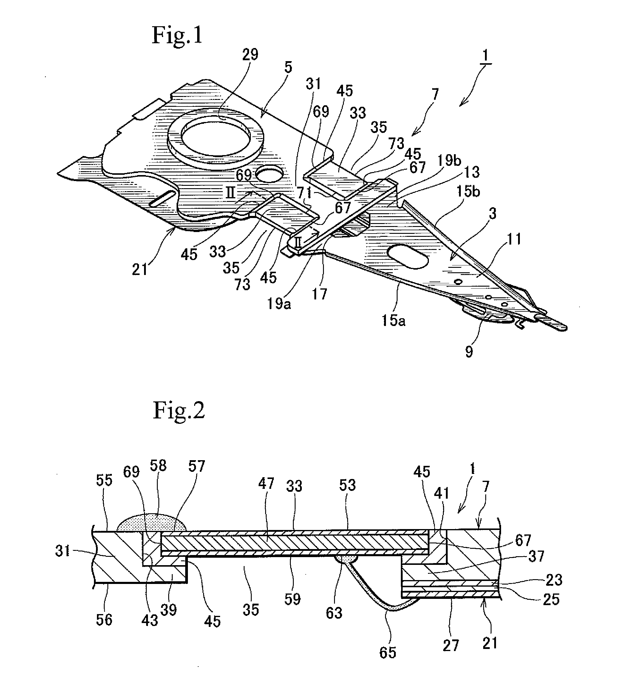
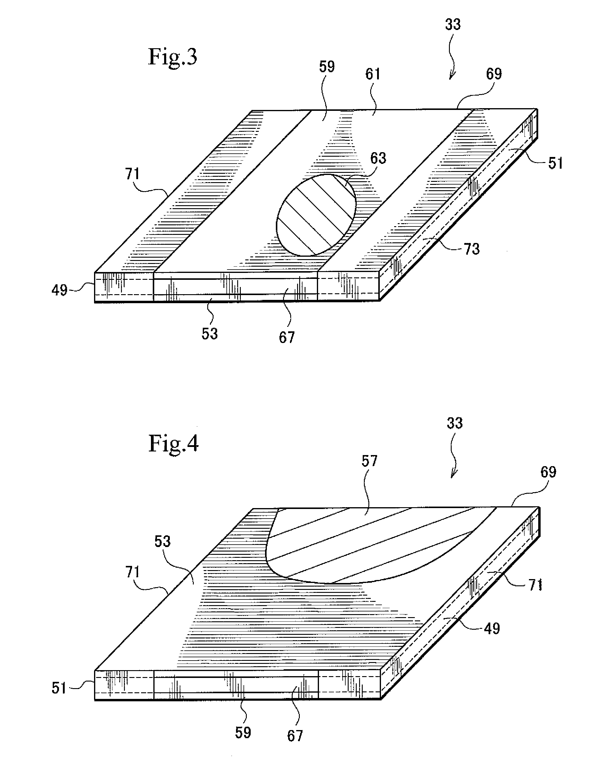
[0032]FIG. 1 is a perspective view illustrating an example of a head suspension having piezoelectric elements according to the present invention, FIG. 2 is a sectional view taken along a line II-II of FIG. 1, FIGS. 3 and 4 are schematic perspective views illustrating the piezoelectric element seen from opposing sides.

[0033]As illustrated in FIGS. 1 and 2, the head suspension 1 has a load beam 3 as a driven part, a base plate 5 as a base, and the piezoelectric actuator 7.

[0034]The load beam 3 applies load onto a read / write head 9 that is supported at a front end of the load beam 3. The load beam 3 includes a rigid part 11 and a resilient part 13. The rigid part 11 is made of a resilient metal thin plate such as resilient stainless steel thin plate having a thickness in the range of about 30 to 150 μm.

[0035]Along each edge of the rigid part 11 in a lateral direction thereof, bends 15a and 15b rise and extend from a front end to a base end of the rigid part 11 in a longitudinal directi...

second embodiment

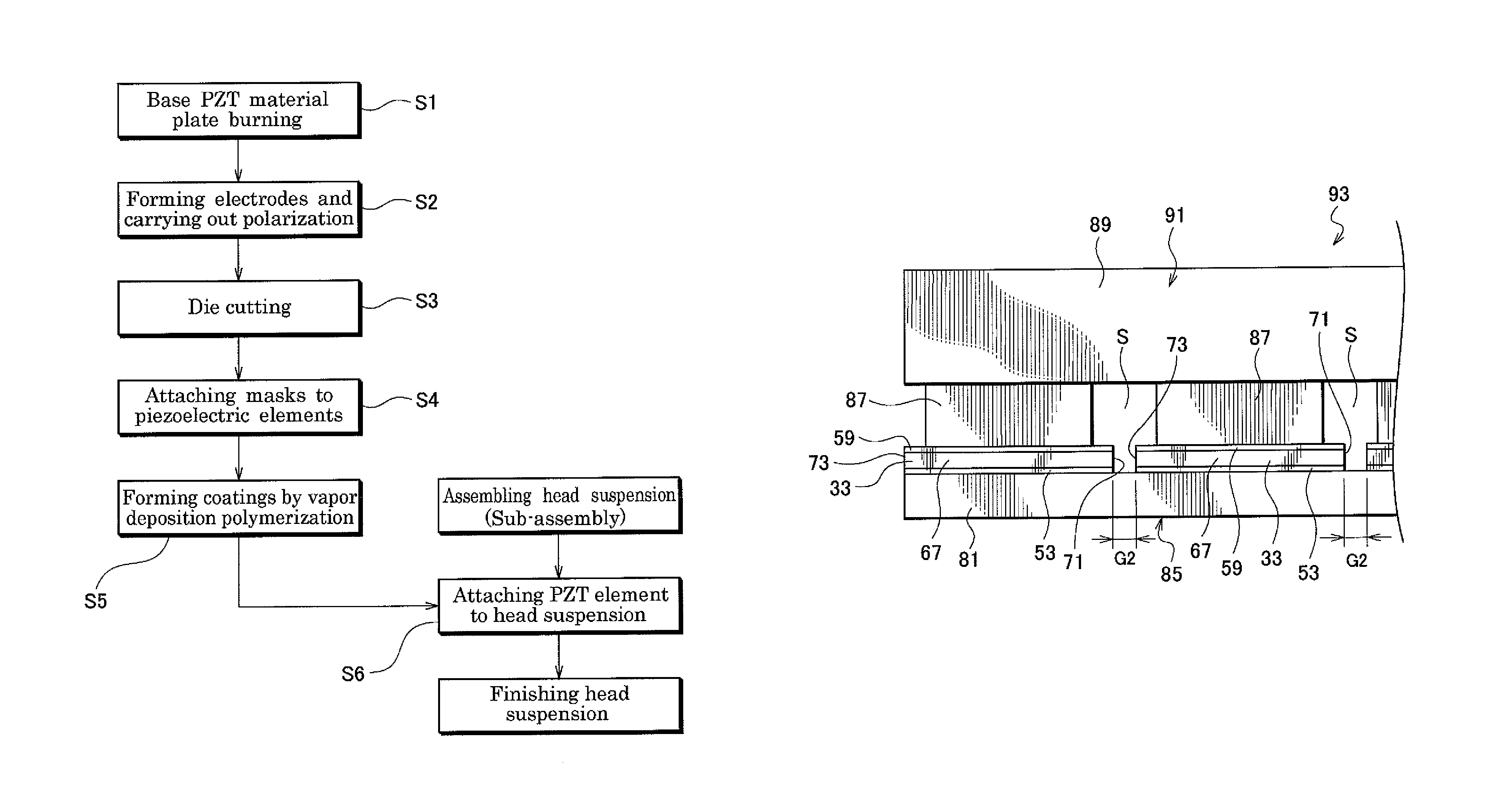
[0143] the spaces SA in the both directions communicate with both gaps G1 and G2 in a thickness direction of the held set 85A or piezoelectric element 33A, respectively. The gaps G1 and G2 forms a closed section together with the spaces SA and are enlarged by the spaces SA.

[0144]The method of the second embodiment is basically the same as the first embodiment. The method of the second embodiment differs from that of the first embodiment in that the masks 87A are used instead of the masks 87 only.

[0145]The second embodiment therefore provides the same effects as the first embodiment.

[0146]Additionally, the method of the second embodiment, each of the gaps G1 and G2 communicates with the space SA in the thickness direction of the held set 85A or the piezoelectric element 33A to form the closed section together with the space SA and be enlarged by the space SA.

[0147]The coatings 59, 51, 121A and 123 A are formed on the peripheral end faces 67, 69, 71 and 73, respectively, so that it pr...

third embodiment

[0151] the unit 95B carries out vapor deposition polymerization based on thermal chemical vapor deposition. Alternatively, the vapor deposition polymerization may be based on plasma chemical vapor deposition, photo chemical vapor deposition, laser chemical vapor deposition, or the like.

[0152]The unit 95B includes a gasification furnace 201, a decomposition furnace 203, a polymerization chamber 205 and a vacuum pump 207 that are connected through a pipe line 209.

[0153]The gasification furnace 201 receives solid or powder raw materials inside and heats and gasifies them. The gasification of the raw materials is carried out under reduced pressure. The raw materials include elements that are constituents of the polymer to form coatings 49 and 51 such as parylene and that are converted into gaseous material by the gasification. The gaseous material is vacuumed by the vacuum pump 207 to pass through the decomposition furnace 203.

[0154]The decomposition furnace 203 decomposes the gaseous m...


PUM

PropertyMeasurementUnit
thicknessaaaaaaaaaa
thicknessaaaaaaaaaa
thicknessaaaaaaaaaa

Abstract

An method of manufacturing a piezoelectric element easily and surely forms polymer coatings on peripheral end faces of the piezoelectric element without deteriorating a yield of the piezoelectric element. The method includes steps of cutting a piezoelectric element out from a base piezoelectric material plate so that peripheral end faces are formed to define a peripheral shape of the piezoelectric element, and forming polymer coatings on at least objective areas of the peripheral end faces of the piezoelectric element by vapor deposition polymerization, respectively.

Description

BACKGROUND OF THE INVENTION[0001]1. Field of the Invention[0002]The present invention relates to a method of manufacturing a piezoelectric element that deforms according to a voltage applied thereto, a manufactured piezoelectric element, a piezoelectric actuator with the piezoelectric element, and a head suspension with the piezoelectric actuator.[0003]2. Description of Related Art[0004]Small-sized, precision information devices are rapidly advancing, and for use with such devices, needs for micro-actuators capable of conducting positioning control for very small distances are increasing. Such micro-actuators are highly needed by, for example, optical systems for correcting focuses and inclination angles, ink-jet printers for controlling ink heads, and magnetic disk drives for controlling magnetic heads.[0005]The magnetic disk drives increase storage capacity by increasing the number of tracks per inch (TPI), i.e., by narrowing the width of each track on a magnetic disk.[0006]Large-...

Claims


Application Information

Patent Timeline
Patent Type & Authority Patents(United States)
IPC IPC(8): G11B5/48H01L41/37H01L41/338H01L41/27H01L41/09H01L41/253C08G59/72C08G73/10H01L41/29G11B5/596G11B21/10
CPCG11B5/483H01L41/094H01L41/253H01L41/27H01L41/338H01L41/37C08G59/72C08G73/10C08G73/1082H01L41/29Y10T29/42Y10T29/49025H10N30/06H10N30/088G11B5/5552G11B5/4873H10N30/04H10N30/05H10N30/87H10N30/092H10N30/883H10N30/2042
Inventor NOJIMA, AKIRA
Owner NHK SPRING CO LTD
Why Eureka
Try Eureka