Method for braking a vehicle
a technology for braking vehicles and clutch discs, applied in mechanical devices, propulsion using engine-driven generators, transportation and packaging, etc., can solve the problems of increasing the energy consumption of brake discs, increasing the cost of conventional clutch mechanisms, and increasing the wear and tear of clutch discs, so as to achieve maximum brake energy, increase rotational speed, and increase the effect of brake torqu
- Summary
- Abstract
- Description
- Claims
- Application Information
AI Technical Summary
Benefits of technology
Problems solved by technology
Method used
Image


Examples
first embodiment
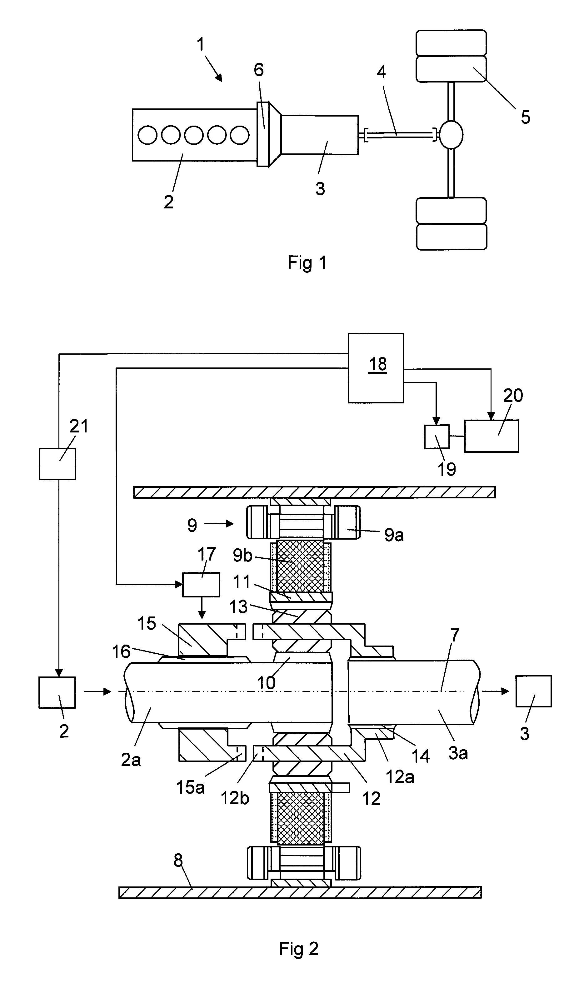
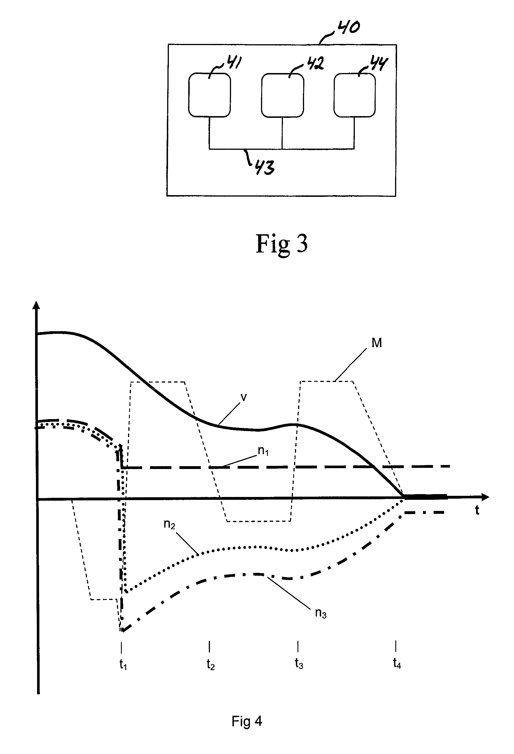
[0037]FIG. 5 shows a flow chart illustrating a method according to the present invention for braking a vehicle driving forward towards stop, in which the vehicle has a propulsion system of the type shown in FIG. 2. It is now also referred to FIG. 4, in which the development of the rotational speeds of the output shaft of the combustion engine, the input shaft of the gearbox and the rotor of the electric machine n1, n2 and n3, respectively, and the speed v of the vehicle and the brake torque M of the electric machine are plotted versus the time for carrying out this method.
[0038]When the method is started, the vehicle is driven forward with the locking means in the locking position and a forward gear and the high range gear engaged in a range gear, not shown, of the vehicle. This means that all three components of planetary gear rotate with the same rotational speed. A need to brake the vehicle towards stop is then detected, for example for stopping the vehicle, which we here assume ...
second embodiment
[0047]A method according to the invention is illustrated in FIG. 6, in which this embodiment differs from the one illustrated in FIG. 5 only with respect to the time after engaging a reverse gear, so that only those method steps are shown there and will now be described. The combustion engine is in this method controlled to deliver a rotational speed n1 of the output shaft thereof which is so dependent on the rotational speed n3 of rotor of the electric machine that the electric machine is controllable to brake the input shaft of the gearbox while generating a maximum electric regenerative power. This maximizes the power by which the electric machine may brake, since the rotational speed of the electric machine may be kept sufficiently high also at the end of the braking procedure.
[0048]A third possibility with respect to the control of the combustion engine during braking is to stop fuel injection into the combustion engine, and when the output shaft of the combustion engine substa...
PUM
 Abstract
Description
Claims
Application Information
 - R&D
- Intellectual Property
- Life Sciences
- Materials
- Tech Scout
- Unparalleled Data Quality
- Higher Quality Content
- 60% Fewer Hallucinations
Browse by: Latest US Patents, China's latest patents, Technical Efficacy Thesaurus, Application Domain, Technology Topic, Popular Technical Reports.
© 2025 PatSnap. All rights reserved.Legal|Privacy policy|Modern Slavery Act Transparency Statement|Sitemap|About US| Contact US: help@patsnap.com