Fluid-working machine with multi-lobe ring cam

a fluid-working machine and multi-lobe technology, applied in machines/engines, positive-displacement liquid engines, gearing, etc., can solve the problems of ring cam working surface degradation, high internal forces and pressures of large fluid-working machines, and high forces received by ring cams from rollers, etc., to achieve the effect of minimal energy loss

Active Publication Date: 2016-05-03
MITSUBISHI HEAVY IND LTD
View PDF54 Cites 10 Cited by
  • Summary
  • Abstract
  • Description
  • Claims
  • Application Information

AI Technical Summary

Benefits of technology

[0025]Thus, as the arc length of the working faces is typically larger than the arc length of the breathing faces, the mean slope of the working faces is typically less than the slope of the breathing faces. The Hertzian stress (e.g. mean Hertzian stress or peak Hertzian stress) in the working surface of ring cam fluid working machines is thus less than would be the case for known fluid-working machines in which the working and breathing faces have a similar arc length. The side loads of the piston against the cylinder are also reduced.
[0057]The invention also extends in a fifth aspect to a method of operating a fluid-working machine comprising providing a fluid-working machine according to the first aspect of the invention and rotating the ring cam relative to the working chambers and thereby causing the volume of the working chambers to vary cyclically.

Problems solved by technology

Large fluid-working machines (such as those suitable for renewable energy generation) are typically subject to particularly high internal forces and pressures.
Consequently the forces received by the ring cam from the rollers are also high, and it is known for the ring cam working surfaces to degrade.
It has been proposed to assemble large scale ring cams from a number of segments, and it is known for excessive wear to occur to the roller and to the working surface due to discontinuities which appear on the working surface under pressure of a roller at the interface between segments.
Thus it is not possible simply to make the rollers larger for the same size of piston, because the piston would anyway only apply force to the roller over the same area, nor to have more or higher amplitude waves, or the machine would become larger and heavier.

Method used


Image

  • Fluid-working machine with multi-lobe ring cam
  • Fluid-working machine with multi-lobe ring cam
  • Fluid-working machine with multi-lobe ring cam

Examples


Embodiment Construction

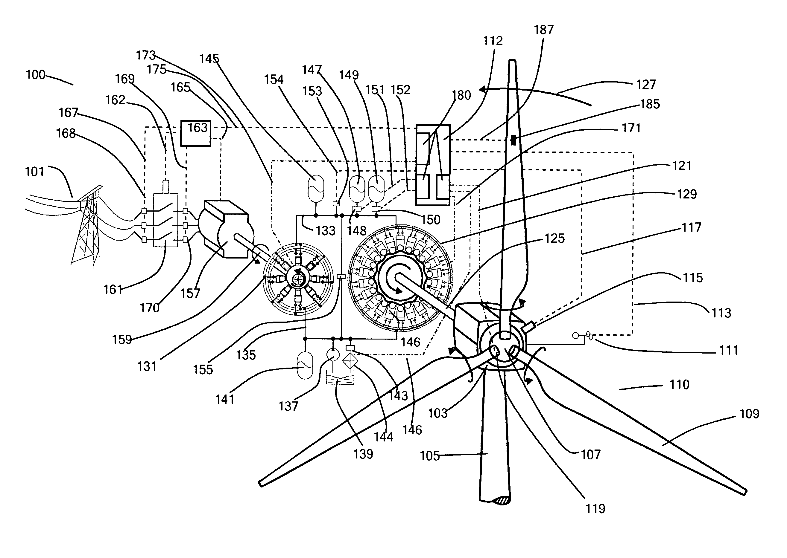
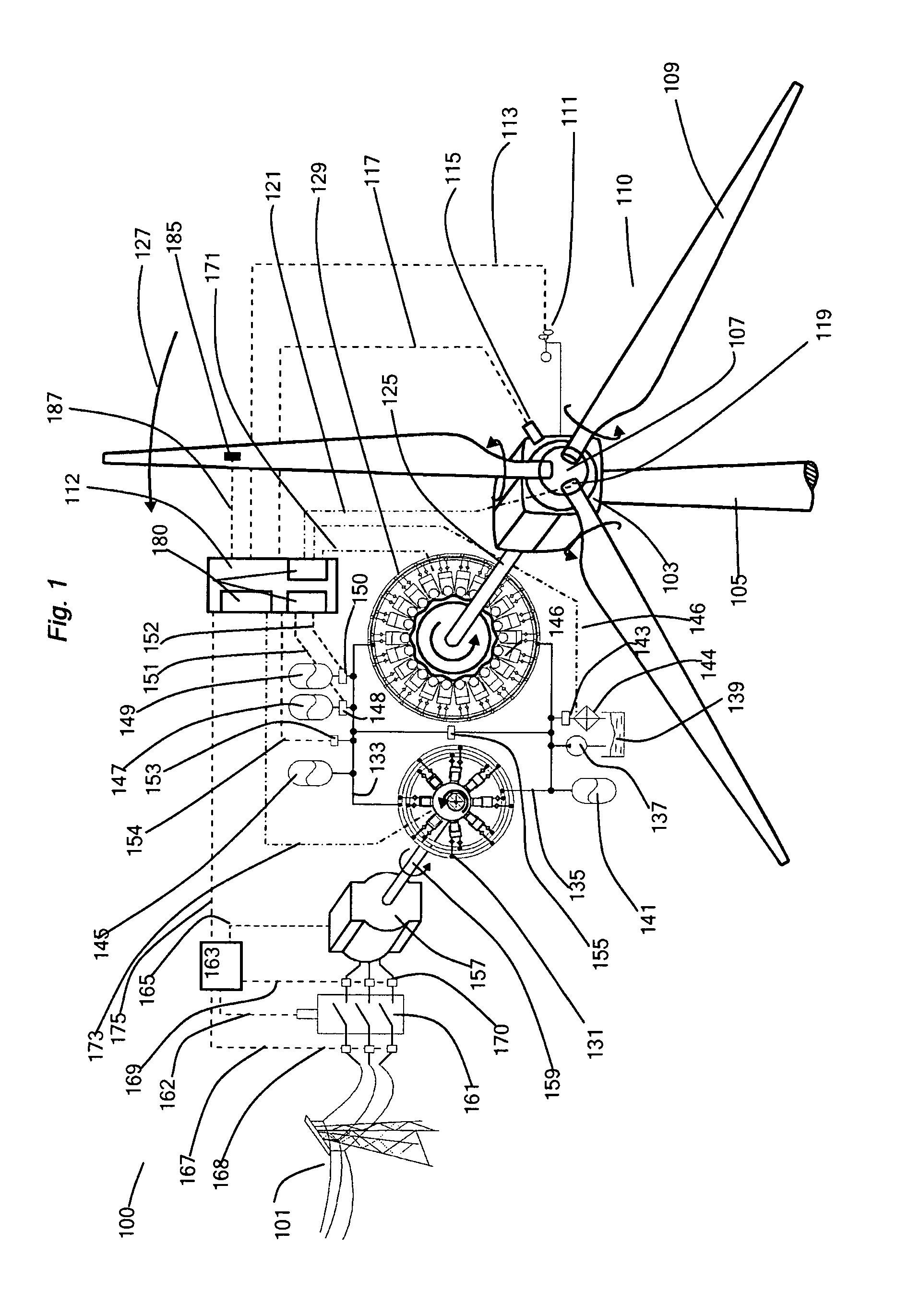
[0067]FIG. 1 illustrates an example embodiment of the invention in the form of a Wind Turbine Generator (WTG, 100), acting as the renewable energy device, and connected to an electricity network (101). The WTG comprises a nacelle (103) rotatably mounted to a tower (105) and having mounted thereon a hub (107) supporting three blades (109) known collectively as the rotor (110). An anemometer (111) attached externally to the nacelle provides a measured wind speed signal (113) to a controller (112). A rotor speed sensor (115) at the nacelle provides the controller with a rotor speed signal (117). In the example system the angle of attack of each of the blades to the wind can be varied by a pitch actuator (119), which exchanges pitch actuation signals and pitch sensing signals (121) with the controller. The invention could be applied to a WTG without a pitch actuator.

[0068]The hub is connected directly to a pump (129), through a rotor shaft (125), acting as the rotatable shaft, which rot...


PUM


Abstract

A fluid-working machine for a renewable energy generation device, the fluid-working machine comprising a ring cam and a plurality of working chambers, the ring cam having an annular working surface extending around an axis of rotation of the ring cam, the annular working surface defining a plurality of waves, each working chamber having a piston, each piston in operative engagement with the ring cam working surface, the ring cam and working chambers being mounted to rotate relative to each other, cycles of working chamber volume being thereby coupled to rotation of the ring cam relative to the working chambers, characterized in that the individual waves of the ring cam working surface have an asymmetric profile.

Description

FIELD OF THE INVENTION[0001]The invention relates to multi-lobe ring cams for fluid-working machines and to fluid-working machines including such ring cams. The invention is particularly applicable where the fluid-working machines are large, for example, pumps or motors in renewable energy extraction devices, such as wind turbines.BACKGROUND TO THE INVENTION[0002]Fluid-working machines include fluid-driven and / or fluid-driving machines, such as pumps, motors, and machines which can function as either a pump or as a motor in different operating modes.[0003]When a fluid-working machine operates as a pump, a low pressure manifold typically acts as a net source of a working fluid and a high pressure manifold typically acts as a net sink for a working fluid. When a fluid-working machine operates as a motor, a high pressure manifold typically acts as a net source of a working fluid and a low pressure manifold typically acts as a net sink for a working fluid. Within this description and th...

Claims


Application Information

Patent Timeline
Patent Type & Authority Patents(United States)
IPC IPC(8): F04B17/02F04B1/00F03C1/30F03C1/053F03D9/00F04B1/04F04B1/053F04B49/06F16H39/02F04C23/02
CPCF04B1/00F03C1/0409F03C1/053F03D9/001F04B1/0413F04B1/053F04B17/02F04B49/065F04C23/02F05B2250/711F05B2250/712F05B2260/406F16H39/02Y02E10/721F03D9/28F03D80/88Y02E10/72F03C1/04F04B1/04
Inventor CALDWELL, NIALL JAMESDUMNOV, DANIIL SERGEEVICHRAMPEN, WILLIAM HUGH SALVINROBERTSON, ALASDAIR IAN FLETCHERSTEIN, UWE BERNHARD PASCALFOX, ROBERT GEORGE
Owner MITSUBISHI HEAVY IND LTD
Why Eureka
Try Eureka