Methods for resistive switching of memristors

Active Publication Date: 2016-05-10
NAT TECH & ENG SOLUTIONS OF SANDIA LLC
View PDF13 Cites 24 Cited by
  • Summary
  • Abstract
  • Description
  • Claims
  • Application Information

AI Technical Summary

Benefits of technology

[0008]The device state (e.g., an ON state, OFF state, ON switching state, and/or OFF switching state) and/or the filament state (e.g., filament conductivity or filament radius) are difficult, if not impossible, to determine experimentally. Thus, models are useful in order to understand one or more parameters of the memory device. Accordingly, the present methods relate to such models. In one exemplary method, the models can be employed to fit I-V or P

Problems solved by technology

The device state (e.g., an ON state, OFF state, ON switching state, and/or OFF switching state) and/or the filament

Method used


Image

  • Methods for resistive switching of memristors
  • Methods for resistive switching of memristors
  • Methods for resistive switching of memristors

Examples


Example

Example 1

Isothermal Switching and Detailed Filament Evolution in Memristive Systems

[0080]Filamentary memristive systems tune their resistance state through the modification of nanoscale conduction channels (see, e.g., Yang J J et al., “Memristive devices for computing,”Nat. Nanotechnol. 2013 January; 8:13-24; Waser R et al., “Redox-based resistive switching memories—nanoionic mechanisms, prospects, and challenges,”Adv. Mater. 2009; 21(25-26):2632-63; and Waser R et al., “Nanoionics-based resistive switching memories,”Nat. Mater. 2007; 6(11):833-40). Such memristive systems or memristors are leading candidates for the future of digital memory storage and are believed to enable entirely new approaches to circuitry and computation (see, e.g., Burr G W, “Overview of candidate device technologies for storage-class memory,”IBM J. Res. Develop. 2008 July; 52(4.5):449-64; Pickett M D et al., “A scalable neuristor built with Mott memristors,”Nat. Mater. 2013 February; 12:114-7; and Jo S H et...

Example

Example 2

Thermal Derivation of the Resistive Model Equations

[0109]To gain further insight into the governing thermal physics and explore this phenomenon, we developed a first principles heat flow model. In steady state, Joule heat is generated uniformly in a cylindrical conducting filament and flows out both vertically through the electrodes and radially through the surrounding oxide: QTot=IV=Qr+Qz (see FIG. 3A).

[0110]In steady state, Joule heat is generated uniformly in a cylindrical conducting filament and flows out both vertically through the electrodes and radially through the surrounding oxide: QTot=IV=Qz+Qr. Integrating vertical heat determines Qz, but requires knowledge of the temperature profile within the filament. Solving the heat equation in cylindrical coordinates as a function of radius r (Incropera FP, “Fundamentals of Heat and Mass Transfer,” 6th ed. 2002: John Wiley & Sons) and with uniform heat generation gives the following:

[0111]T⁡(r)=σ⁢⁢V2⁢rF24⁢dO2⁢kF⁢(1-r2rF2)+T...

Example

Example 3

Discussion of Filament Ruptures

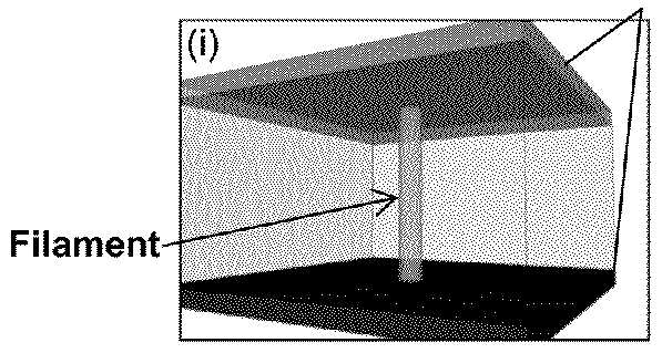
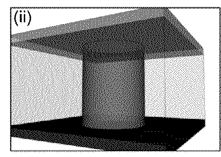
[0128]Filament ruptures have been observed in TEM experiments, as well as predicted by finite element simulations. In contrast, the model presented herein predicts a ‘quasi-uniform’ depletion of oxygen vacancies in the conducting filament, as opposed to the localized depletion associated with ruptures. In fact, the model presented here is consistent with ruptures, and predicts them to occur, however we believe this phenomenon takes place at much later stages of OFF / RESET switching. Below, we present a simple thermal / electrical experiment that we believe clearly demonstrates this viewpoint in our data. The validity of this viewpoint can be tested by considering the difference in power required to switch the same filament configuration ON or OFF. FIG. 8 shows schematics of the filament during ON state heating (SET switching, top schematic), OFF state switching (RESET switching, center schematic), and non-rupture OFF heating (bottom schematic).

[0...


PUM


Abstract

The present invention is directed generally to resistive random-access memory (RRAM or ReRAM) devices and systems, as well as methods of employing a thermal resistive model to understand and determine switching of such devices. In particular example, the method includes generating a power-resistance measurement for the memristor device and applying an isothermal model to the power-resistance measurement in order to determine one or more parameters of the device (e.g., filament state).

Description

CROSS-REFERENCE TO RELATED APPLICATION[0001]This application is a continuation-in-part of prior U.S. application Ser. No. 14 / 462,472, filed Aug. 18, 2014, which in turn claims the benefit of U.S. Provisional Application No. 61 / 866,690, filed Aug. 16, 2013, each of which is hereby incorporated by reference in its entirety.STATEMENT OF GOVERNMENT INTEREST[0002]This invention was made with Government support under contract no. DE-AC04-94AL85000 awarded by the U.S. Department of Energy to Sandia Corporation. The Government has certain rights in the invention.REFERENCE TO A COMPUTER PROGRAM LISTING APPENDIX[0003]A computer program listing appendix including an ASCII formatted file accompanies this application. The appendix includes a file named “SD13146_Appendix.txt,” created on Dec. 23, 2014 (size of 21.9 kilobytes), which is hereby incorporated by reference in its entirety.COPYRIGHT NOTICE[0004]A portion of the disclosure of this patent document contains material which is subject to co...

Claims


Application Information

Patent Timeline
IPC IPC(8): G11C11/00G11C13/00
CPCG11C13/0011G11C13/0069G11C13/004G11C2213/15
Inventor MICKEL, PATRICK R.JAMES, CONRAD D.LOHN, ANDREWMARINELLA, MATTHEWHSIA, ALEXANDER H.
Owner NAT TECH & ENG SOLUTIONS OF SANDIA LLC
Why Eureka
Try Eureka