
Method of plating stainless steel and plated material

a technology of stainless steel and plated material, which is applied in the direction of superimposed coating process, transportation and packaging, coatings, etc., can solve the problems of corroding layer, corrosion reaches the surface and the sacrifice corrosive effect may not prevent the progress of corrosion of the steel substrate, so as to prevent the corrosion of the stainless steel substrate from pitting

Active Publication Date: 2016-05-24
TOYOTA JIDOSHA KK
View PDF32 Cites 15 Cited by
  • Summary
  • Abstract
  • Description
  • Claims
  • Application Information

AI Technical Summary

Benefits of technology

The present invention provides a way to prevent stainless steel from getting pitted and corrosion in very aggressive environments. This makes it easier to plate materials onto stainless steel and use it in various applications.

Problems solved by technology

However, under a harsh corrosive environment such as a strongly acidic atmosphere, simply applying plating with the sacrificial corrosive effect may not sufficiently prevent progress of corrosion of the steel substrate.
However, even if a plating layer such as a nickel plating layer is provided over the surface of the stainless steel as disclosed in JP 2004-205059, the plating layer may corrode if it is exposed to a strongly acidic environment at, for example a pH of 2-3 for a long period.
If corrosion of the plating layer further progresses, corrosion reaches the surface of the stainless steel substrate (base material).
When corrosion further progresses in the thickness direction of the stainless steel from such a state, corrosion holes pass through the interior of the stainless steel.
As a result, a part made of the stainless steel may lose its original function.

Method used


Image

  • Method of plating stainless steel and plated material
  • Method of plating stainless steel and plated material
  • Method of plating stainless steel and plated material

Examples


example 1

[0052]A plated material (test sample) in which plating was applied to a stainless steel was fabricated as described in the following.

[0053][Passivation Film Removal Step]

[0054]As a stainless steel to be plated, an austenitic stainless steel (JIS: SUS304) of 40 mm×40 mm×0.8 mm thickness was prepared. Next, as a pretreatment, the stainless steel substrate was washed by water, dipped into a hydrochloric acid solution of a concentration of 210 g / L at 45° C. for 3 minutes, subsequently washed by water, and further dipped into a sulfuric acid solution of a concentration of 210 g / L at 60° C. for 1 minute. Passivation films on the surface of the stainless steel substrate was thereby removed.

[0055][First Plating Step]

[0056]Next, electroless Ni—B plating was conducted as a first plating step. Specifically, an Ni—B plating liquid (Okuno Chemical Industries Co., Ltd.: Top Chem Alloy 66-LF) made of 25 g / L of nickel sulfate, several g / L of DMBA, 10 g / L of organic acid, and other additives was adj...

example 2

[0065]A plated material was fabricated in a manner similar to the example. This plated material differs from Example 1 in that an austenitic stainless steel (JIS: SUS316) further containing Mo was used as the stainless steel substrate and a strike plating step was conducted instead of the passivation film removal step. Specifically, the stainless steel was dipped into a solution of Ni concentration of 60 g / L and hydrochloric acid concentration of 35 g / L and underwent removal of passivation films by application of electric current of 1.5 A / dm2 for 5 minutes at room temperature. The surface of the stainless steel substrate from which the passivation films had been removed was coated with an electrolytic strike plating layer to a thickness of 0.3 μm.


PUM

PropertyMeasurementUnit
temperatureaaaaaaaaaa

Abstract

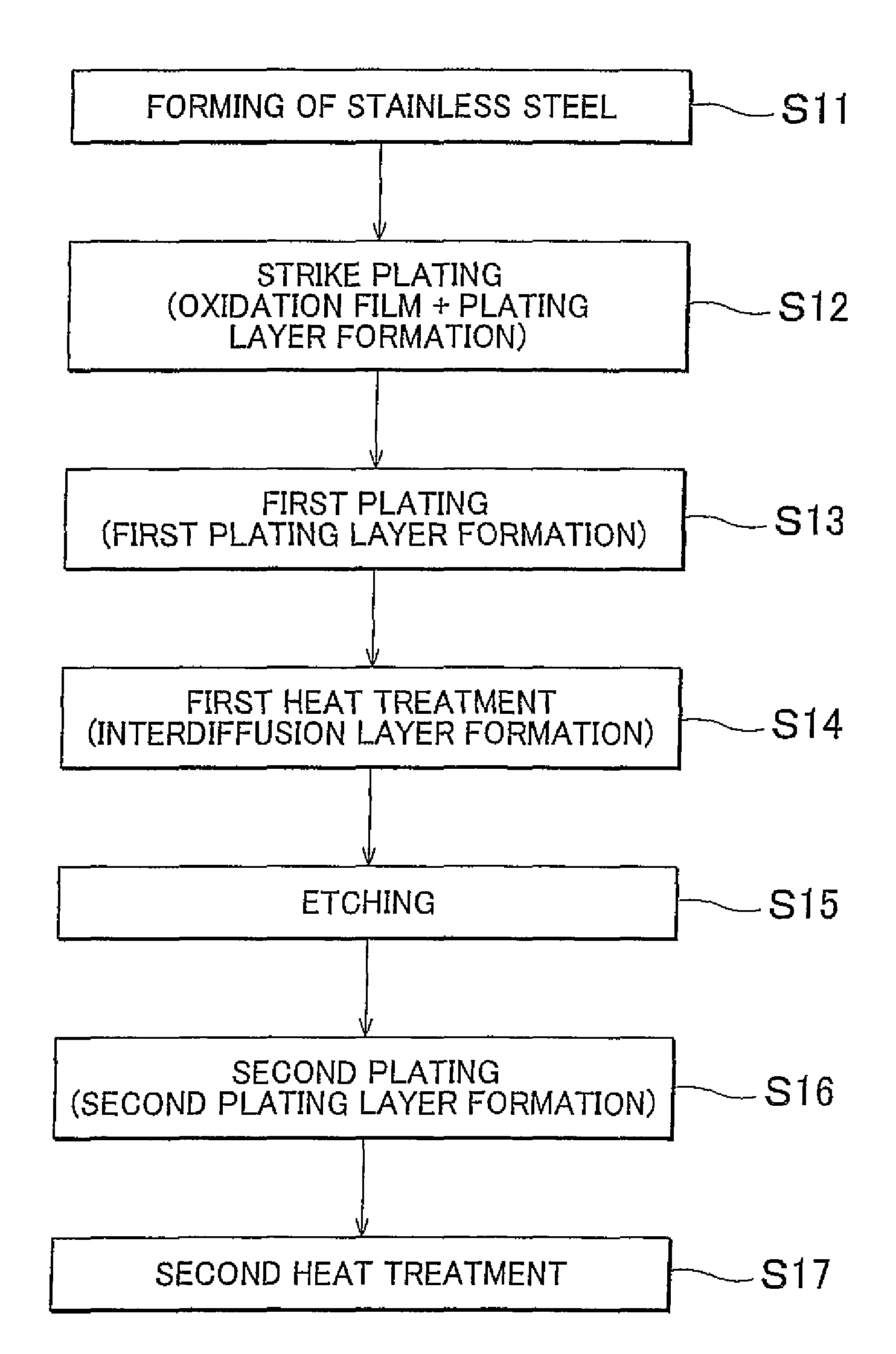
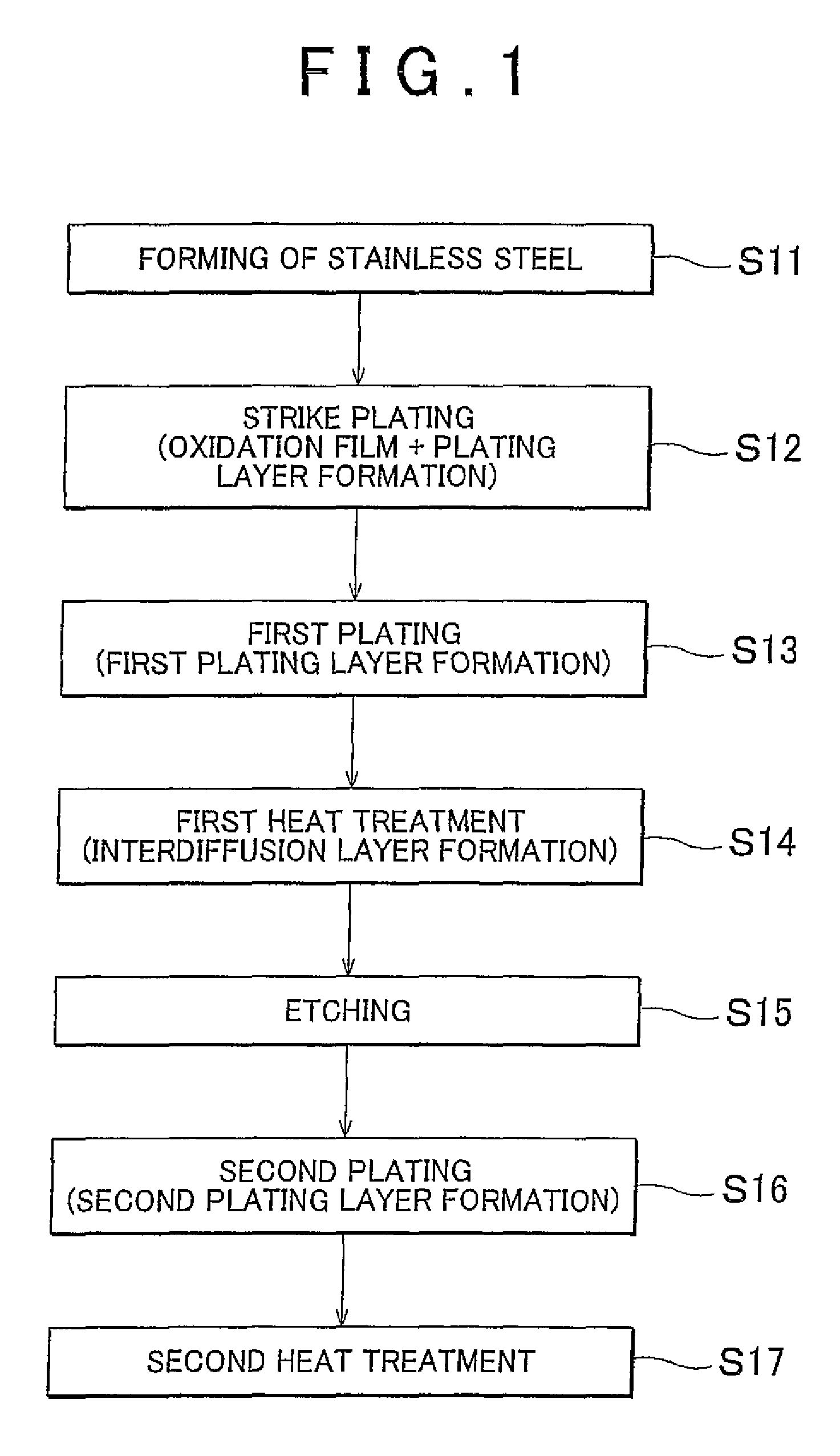
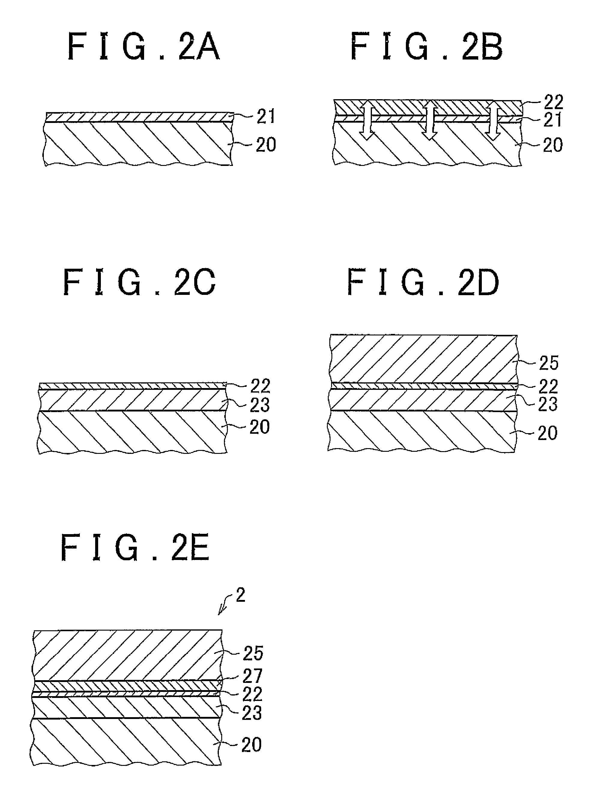
The method of plating a stainless steel substrate including depositing a first plating metal layer over the stainless steel substrate), forming an interdiffusion layer in which elements of the stainless steel substrate and elements of the first plating metal layer interdiffuse, by applying a heat treatment to the stainless steel substrate coated by the first plating metal layer, and coating a second plating metal layer over the surface of the stainless steel substrate over which the interdiffusion layer is coated.

Description

FIELD OF THE INVENTION[0001]The present invention relates to a method of plating a surface of a stainless steel and a plated material therefor, and particularly to a method of plating a highly corrosion-resistant stainless steel and a plated material.BACKGROUND OF THE INVENTION[0002]The surfaces of steel products under corrosive environments, such as automotive parts, are coated with plating films (plating metal layers) such as zinc, nickel, and chromium to reduce corrosion of the steel substrate. Under a mildly corrosive environment, steel is generally coated with zinc plating or the like that provides sacrificial corrosive effect. However, under a harsh corrosive environment such as a strongly acidic atmosphere, simply applying plating with the sacrificial corrosive effect may not sufficiently prevent progress of corrosion of the steel substrate.[0003]Accordingly, a method has been adopted in which a highly corrosion-resistant stainless steels are used in steel products and furthe...

Claims


Application Information

Patent Timeline
Patent Type & Authority Patents(United States)
IPC IPC(8): C25D5/10C25D5/14C25D5/34C25D5/36C25D7/00C23C28/02C25D5/50
CPCC25D5/10C23C28/02C23C28/028C25D5/14C25D5/34C25D5/36C25D5/50C25D7/00Y10T428/12944C25D5/619
Inventor BESSHO, TAKESHI
Owner TOYOTA JIDOSHA KK
Learn More