
Static dissipation in composite structural components

a technology of composite structural components and static charge, which is applied in the direction of connecting contact member materials, mechanical equipment, coatings, etc., can solve the problems of igniting a flammable atmosphere in the region surrounding equipment, and achieve the effects of dissipating static build-up, dissipating static energy build-up, and dissipating electrostatic charg

Active Publication Date: 2016-05-24
CHEVROU USA INC
View PDF26 Cites 1 Cited by
  • Summary
  • Abstract
  • Description
  • Claims
  • Application Information

AI Technical Summary

Benefits of technology

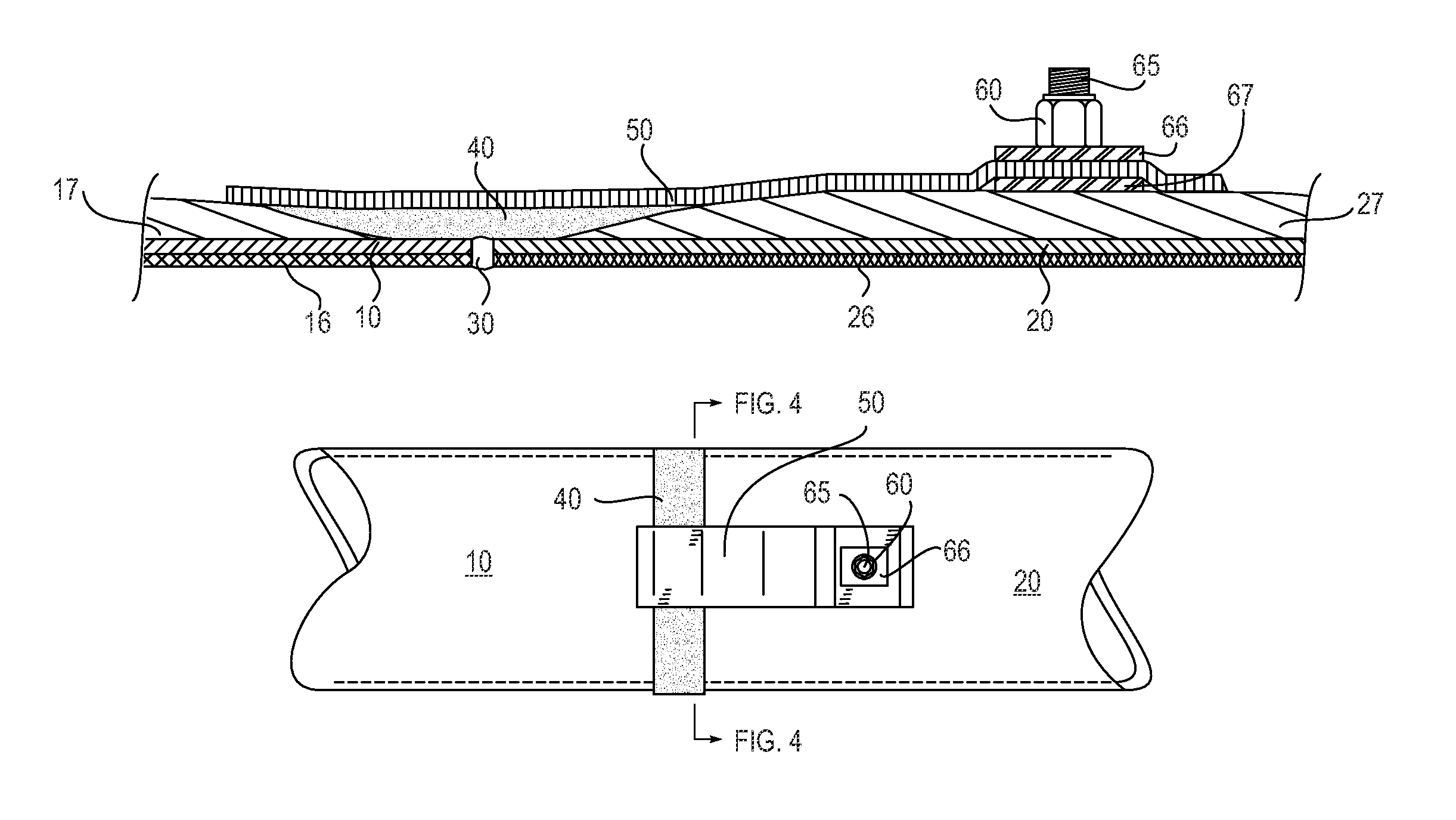
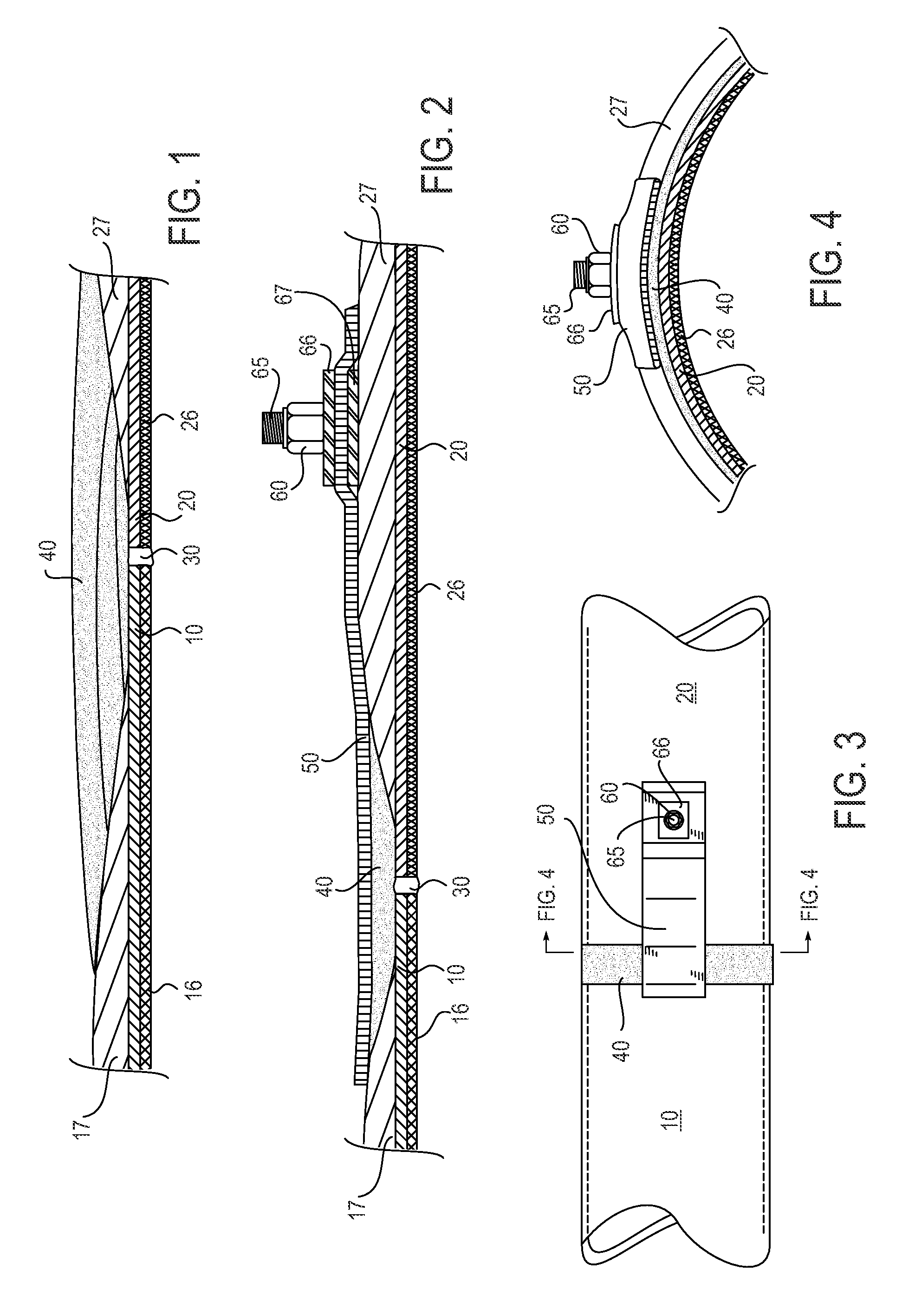
[0006]In one aspect, a pipe system for containing fluids such as corrosive petroleum products, having conductivity of less than 10,000 pS / m is provided. The pipe system has at least two pipe sections, each comprising a structural layer and a corrosion resistant layer. The corrosion resistant layer has at least a conductive surface area in contact with the fluid, with the conductive surface area defining an electrical pathway extending a portion of the length of the pipe structure. Each pipe section has a tapered end exposing a portion of the corrosion resistant / conductive layer. The two pipe sections are joined at the tapered ends by a conductive adhesive overlay. The conductive adhesive overlay is electrically connected to a grounding device, wherein the grounding device helps dissipate build-up of electrostatic charge in the pipe system carrying the fluid, for a total resistance to ground of less than one MEG OHM (10^6 ohms) from all points throughout the system.

Problems solved by technology

Static charge accumulation can also give rise to external discharges, potentially igniting a flammable atmosphere in the region surrounding the equipment.

Method used


Image

  • Static dissipation in composite structural components
  • Static dissipation in composite structural components

Examples


Embodiment Construction

[0012]The following terms will be used throughout the specification and will have the following meanings unless otherwise indicated.

[0013]“Petroleum products” refer to natural gas; natural and synthetic liquid hydrocarbon products including but not limited to biodegraded oils, crude oils, refined products including gasoline, other fuels, and solvents; and semi-solid / solid hydrocarbon products including but not limited to tar sand, bitumen, etc.

[0014]“Structural components” refer to pipelines, a pipe system, tubings, vessels, reactors, transfer lines, process piping, processing equipment including but not limited to distillation columns, and the like. In one embodiment, the structural component is a section of pipe for transporting petroleum products.

[0015]“Structural layer” refers to a layer that creates or provides the structural support for a structural component.

[0016]“Corrosion resistant layer” refers to the layer of the structural component that is in contact with the petroleum...


PUM

PropertyMeasurementUnit
conductivityaaaaaaaaaa
total resistanceaaaaaaaaaa

Abstract

A method to prevent the accumulation of static electricity in a pipe system for containing corrosive petroleum products is provided, for a total resistance of less than 1 MEG ohms to ground from all points. The pipe system has at least two pipe sections, each comprising a structural layer and a corrosion resistant layer. The corrosion resistant layer has at least a conductive surface area in contact with the fluid, with the conductive surface area defining an electrical pathway extending a length of the pipe section. Each pipe section has a tapered end exposing a portion of the corrosion resistant layer. The method comprises joining the two pipe sections at the tapered ends by a conductive adhesive overlay, and electrically connecting the conductive adhesive overlay to a grounding device, wherein the grounding device helps dissipate build-up of electrostatic charge in the pipe system carrying the fluid.

Description

CROSS-REFERENCE TO RELATED APPLICATIONS[0001]This application claims benefit under 35 USC 119 of U.S. Provisional Patent Application No. 61 / 522,822 with a filing date of Aug. 12, 2011. This application claims priority to and benefits from the foregoing, the disclosure of which is incorporated herein by reference.TECHNICAL FIELD[0002]The invention relates to static charge dissipating structural components, including composite pipes, and methods for joining composite components as to promote static dissipation.BACKGROUND[0003]Electrostatic or static charges can be generated both on the inside and outside of structural components such as pipes, vessels, etc. One source of static charge generation and accumulation results from the flow of fluids with conductivities of less than 10,000 pS / m inside non-conducting structural components. Static discharges can occur inside equipment such as insulating pipes, so counter-measures are necessary when operating a pipe that is only partially fille...

Claims


Application Information

Patent Timeline
Patent Type & Authority Patents(United States)
IPC IPC(8): H01R43/00F16L25/01F16L13/10F16L58/10H01R4/60
CPCF16L13/103F16L25/01F16L58/1009H01R4/60Y10T29/49117
Inventor SCHMIDT, KYLE WARRENRAPOZA, RANDAL JOSEPHTHOMPSON, BRIAN GENENICCOLLS, EDWIN HALL
Owner CHEVROU USA INC
Learn More