Revolving apparatus for work vehicle

a technology for working vehicles and rotating apparatuses, which is applied in mechanical apparatuses, transportation and packaging, brake systems, etc., to achieve the effect of reliably stopping the revolution and not increasing the overall height of the apparatus

Active Publication Date: 2016-05-31
KOMATSU LTD
View PDF18 Cites 1 Cited by
  • Summary
  • Abstract
  • Description
  • Claims
  • Application Information

AI Technical Summary

Benefits of technology

[0011]In light of the problems encountered with conventional revolving apparatuses, it is an object of the present invention to provide a revolving apparatus having a brake unit whose performance is improved by ensuring a long stroke of the spring member.
[0014]When concave components are thus provided to both the housing and the piston, as compared to a conventional configuration in which a concave component is provided only to the piston, it is possible to increase the natural length of the spring member without increasing the height of the revolving apparatus, and the stroke can be lengthened. Accordingly, this prevents buckling of the spring member and increases the pressing force of the piston.
[0015]Furthermore, since there is no need to increase the height of the revolving apparatus itself, there is also no need to change the height of the walkway that partially overlaps the revolving apparatus in plan view, or the routing of pipes, so the stroke of the spring member can be lengthened easily.
[0017]In the manufacture of the brake unit, the spring member is placed in the second concave component of the piston, after which the housing is disposed from above the piston so that the spring member will fit into the first concave component. Accordingly, the spring member will fit into the first concave component more easily if the inside diameter of the first concave component is formed greater than the inside diameter of the second concave component, and this makes it easier to dispose the housing from above the piston.
[0019]Here, providing the positioning member fixes the position of the piston with respect to the housing in a direction perpendicular to the movement direction of the piston. Therefore, even if a force is generated that would cause positional offset with the housing in a direction perpendicular to the movement direction of the piston, such as during movement of the piston, this force can be received by the positioning member. This prevents excessive force from being exerted on the spring member.
[0023]The present invention provides a revolving apparatus having a brake unit that can ensure a long stroke of the spring members, without increasing the overall height of the apparatus.

Problems solved by technology

However, the following problems were encountered with the conventional revolving apparatus discussed above.
However, it can be a problem if the height of the revolving apparatus is increased too much, so that it sticks out on the upper revolving unit, such as when there is a walkway for the operator or other people on the upper revolving unit where the apparatus is installed.

Method used


Image

  • Revolving apparatus for work vehicle
  • Revolving apparatus for work vehicle
  • Revolving apparatus for work vehicle

Examples


Embodiment Construction

)

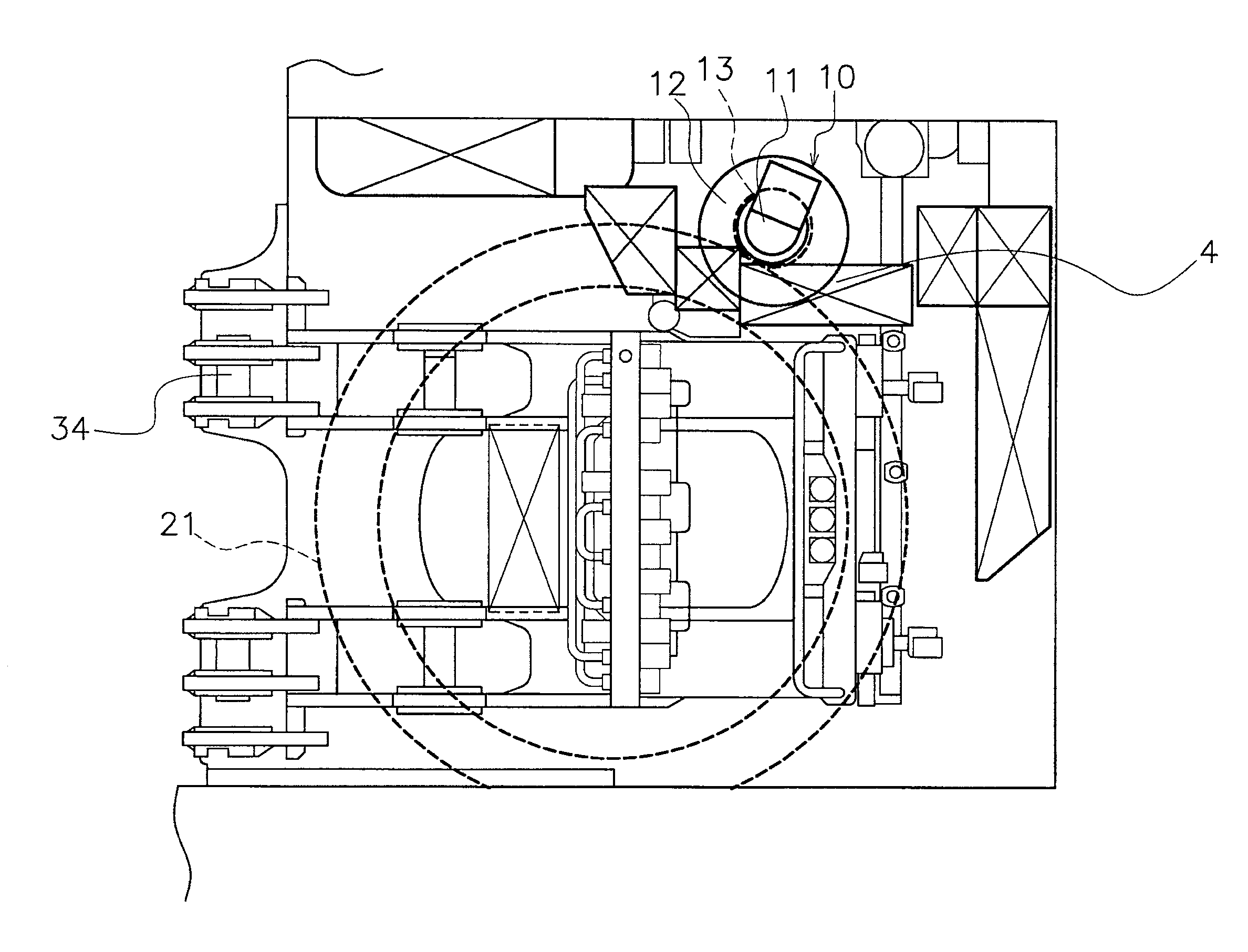
[0035]The revolving apparatus of a work vehicle pertaining to an embodiment of the present invention will be described through reference to FIGS. 1 to 10.

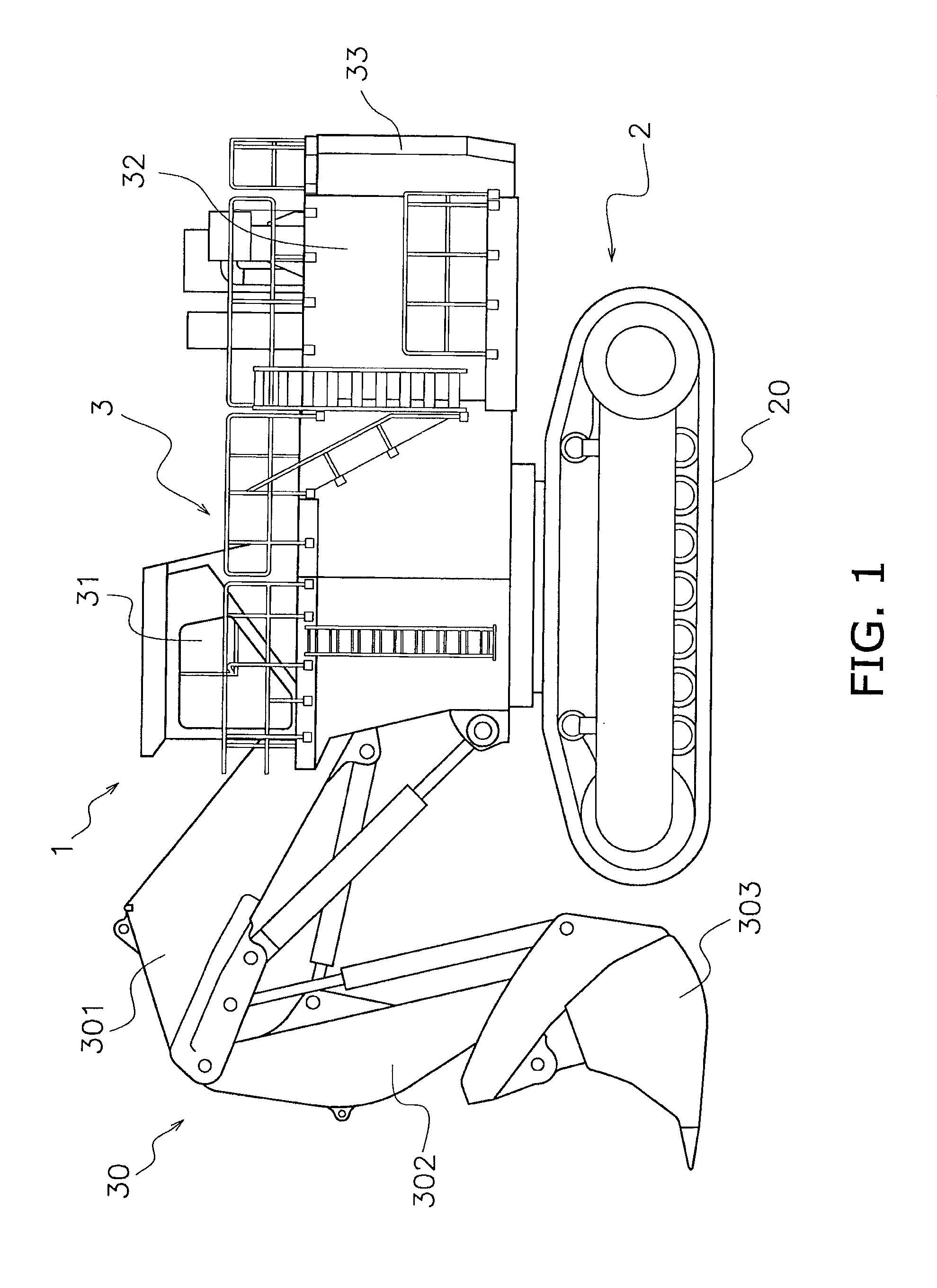
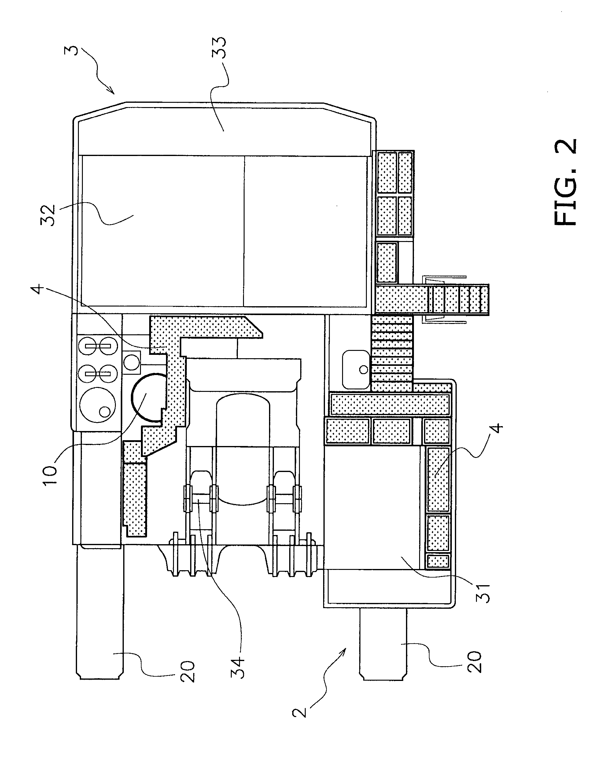
[0036]FIG. 1 is a side view of the hydraulic excavator in this embodiment. FIG. 2 is a partial plan view of the hydraulic excavator in this embodiment, excluding the work implement.

[0037]As shown in FIG. 1, a hydraulic excavator 1, which is an example of a work vehicle, comprises a lower traveling unit 2 having crawlers 20 provided on the left and right ends in the travel direction, and an upper revolving unit 3 disposed at the upper part of the lower traveling unit 2. The upper revolving unit 3 is provided with a work implement 30, a driver's compartment 31, an engine compartment 32, a counter weight 33, and so forth. This work implement 30 has a boom 301 that is bent in the middle portion, an arm 302 attached to the distal end of the boom 301, and a bucket 303 attached to the distal end of the arm 302. As shown in FIG. 2, work i...


PUM


Abstract

A revolving apparatus for a work vehicle includes a drive unit, a brake unit under the drive unit, a deceleration unit under the brake unit, and an output unit under the deceleration unit. The brake unit has a brake main body that stops revolution, a housing, a piston and a spring. The housing has a first face with a first concave component. The piston has a second face opposite the first face with a second concave component. The piston is disposed between the brake main body and the housing, and is movable with respect to the housing in order to actuate the brake main body. The spring member has two ends held in the first and second concave components. The first and second concave components have cylindrical shapes. The inside diameter of the first concave component is greater than the inside diameter of the second concave component.

Description

CROSS-REFERENCE TO RELATED APPLICATIONS[0001]This application is a U.S. National stage application of International Application No. PCT / JP2013 / 067402, filed on Jun. 25, 2013. This U.S. National stage application claims priority under 35 U.S.C. §119(a) to Japanese Patent Application No. 2012-268436, filed in Japan on Dec. 7, 2012, the entire contents of which are hereby incorporated herein by reference.BACKGROUND[0002]1. Field of the Invention[0003]The present invention relates to a revolving apparatus for a work vehicle.[0004]2. Background Information[0005]An upper revolving unit having a work implement or the like, and a lower traveling unit having crawlers are provided to a work vehicle such as a hydraulic excavator. In the case of a hydraulic excavator, for example, the work implement is constituted by a boom, an arm, a bucket, or the like.[0006]A revolving apparatus comprising a swing motor, swing machinery, and an output pinion is provided in order to make the upper revolving u...

Claims


Application Information

Patent Timeline
Patent Type & Authority Patents(United States)
IPC IPC(8): B62D33/00E02F9/22B60T1/06F16D55/24E02F9/08E02F9/12F16D55/00F16D121/06
CPCE02F9/128B60T1/062E02F9/0833E02F9/2275F16D55/24F16D2055/0058F16D2121/06
Inventor KISHINAMI, YOUSUKE
Owner KOMATSU LTD
Why Eureka
Try Eureka