Heat transfer tube and cracking furnace using the heat transfer tube

a heat transfer tube and cracking furnace technology, applied in indirect heat exchangers, lighting and heating apparatus, transportation and packaging, etc., can solve the problems of unusually large heat resistance of fins and similar less effective fins, so as to improve the tangential speed of fluid, enhance heat transfer, and strengthen the turbulence of heat transfer tubes

Active Publication Date: 2016-06-07
CHINA PETROCHEMICAL CORP +1
View PDF18 Cites 2 Cited by
  • Summary
  • Abstract
  • Description
  • Claims
  • Application Information

AI Technical Summary

Benefits of technology

[0010]In the heat transfer tube according to the present disclosure, under the action of the twisted baffle, fluid flows along the twisted baffle and turns into a rotating flow. A tangential speed of the fluid destroys the boundary layer so as to achieve the purpose of enhancing heat transfer.
[0019]Compared with the prior art, the present disclosure excels in the following aspects. To begin with, the arrangement of the twisted baffle in the heat transfer tube turns the fluid flowing along the twisted baffle into a rotating fluid, thus improving the tangential speed of the fluid, destroying the boundary layer and achieving the purpose of enhancing heat transfer. Next, the plurality of holes provided on the twisted baffle can change the flow direction of the fluid so as to strengthen the turbulence in the heat transfer tube and achieve the object of enhancing heat transfer. Besides, these holes further reduce the resistance in the flow of the fluid, so that pressure loss is further decreased. Moreover, coke pieces carried in the fluid can also move downstream through these holes, which promotes the discharge of the coke pieces. When one single region of the heat transfer tube is provided with a plurality of twisted baffles parallel to one another, which define an enclosed circle viewed from one end of the heat transfer tube, a central portion of the heat transfer tube actually forms a channel, which can lower pressure loss and is favorable for rapid discharge of the coke pieces. Furthermore, along the trajectory of the circle a casing is arranged. Therefore, the casing, twisted baffle and inner wall of the heat transfer tube form a spiral cavity together, wherein the fluid is turned into a complete rotating flow, which further improves the tangential speed of the fluid, thus further enhancing the heat transfer and reducing formation of coke on the wall of the heat transfer tube. In addition, the casing can support the twisted baffle, thereby improving the stability and impact resistance of the twisted baffle.

Problems solved by technology

Although this boundary layer is very thin, the heat resistance thereof is unusually large.
However, as the coke on the inner surface of the furnace pipe is increased, these fins will similarly get less effective.

Method used


Image

  • Heat transfer tube and cracking furnace using the heat transfer tube
  • Heat transfer tube and cracking furnace using the heat transfer tube
  • Heat transfer tube and cracking furnace using the heat transfer tube

Examples


example 1

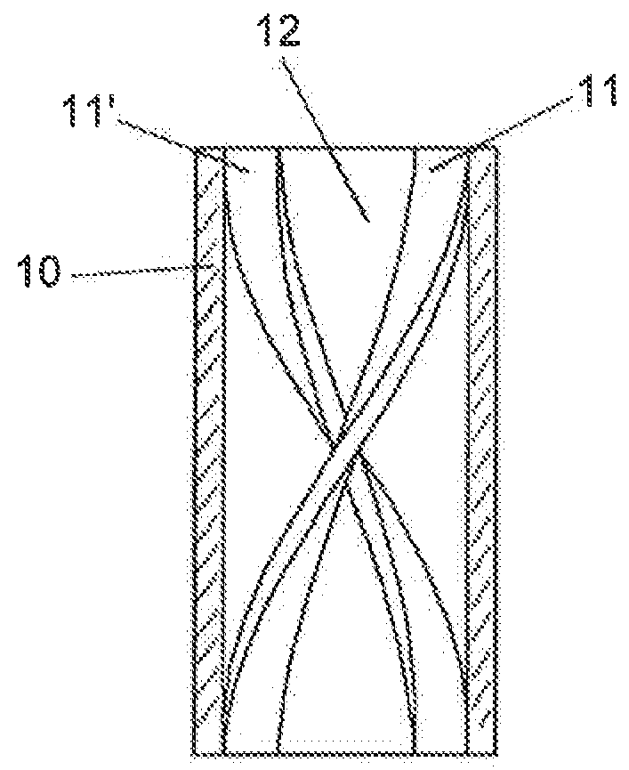
[0040]The radiant coil of the cracking furnace is arranged with 6 heat transfer tubes 10 as indicated in FIG. 1. The inner diameter of each of the heat transfer tubes 10 is 51 mm. The diameter ratio of the enclosed circle to the heat transfer tube is 0.6:1. The twisted baffle has a twist angle of 180° and a twist ratio of 2.5. The distance between two adjacent heat transfer tubes 10 is 50 times as large as the inner diameter of the heat transfer tube. Experiments have found that the heat transfer load of the radiant coil is 1,270.13 KW and the pressure drop is 70,180.7 Pa.

example 2

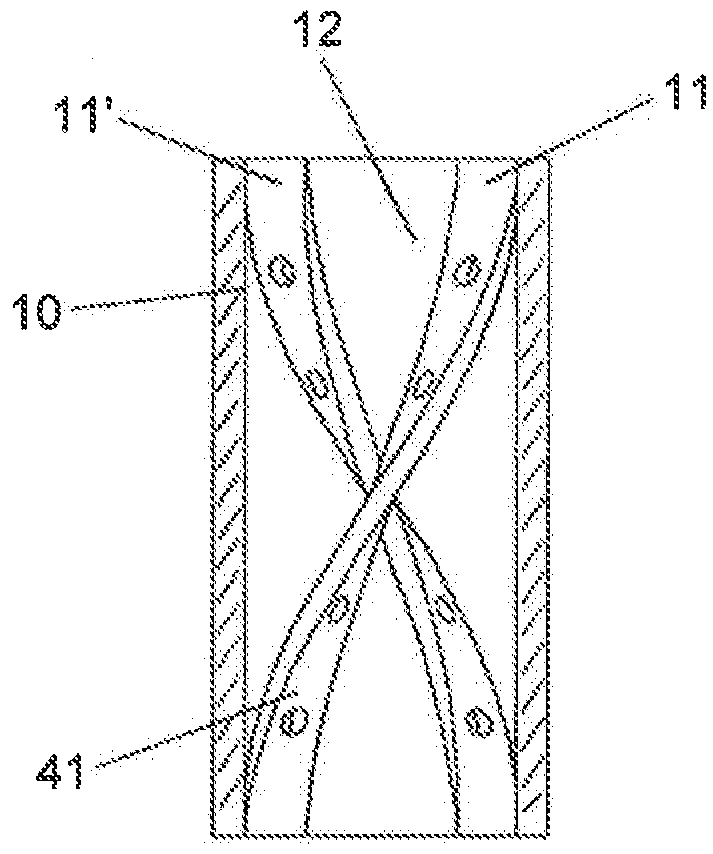
[0041]The radiant coil of the cracking furnace is arranged with 6 heat transfer tubes 10 as indicated in FIG. 2. The inner diameter of each of the heat transfer tubes 10 is 51 mm. The diameter ratio of the enclosed circle to the heat transfer tube is 0.6:1. The twisted baffle has a twist angle of 180° and a twist ratio of 2.5. The distance between two adjacent heat transfer tubes 10 is 50 times as large as the inner diameter of the heat transfer tube. Experiments have found that the heat transfer load of the radiant coil is 1,267.59 KW and the pressure drop is 70,110.5 Pa.


PUM

PropertyMeasurementUnit
twist angleaaaaaaaaaa
inner diameteraaaaaaaaaa

Abstract

The present disclosure relates to a heat transfer tube and a cracking furnace using the heat transfer tube. The heat transfer tube comprises a twisted baffle arranged in an inner wall of the tube, said twisted baffle extending spirally along an axial direction of the heat transfer tube. The twisted baffle defines a closed circle viewed from an end of the heat transfer tube. Along the trajectory of the circle a casing is arranged, which is fixedly connected to a radial inner end of the twisted baffle. The twisted baffle is provided with a plurality of holes. The heat transfer tube according to the present disclosure has a good heat transfer effect and small pressure loss.

Description

[0001]This application claims benefit of priority under 35 U.S.C. §119 to Chinese Patent Application No. CN 201210426112.4, filed Oct. 30, 2012, the contents of which are also incorporated herein by references.TECHNICAL FIELD[0002]The present disclosure relates to a heat transfer tube which is especially suitable for a heating furnace. The present disclosure further relates to a cracking furnace using the heat transfer tube.TECHNICAL BACKGROUND[0003]Cracking furnaces, the primary equipment in the petrochemical industry, are mainly used for heating hydrocarbon material so as to achieve cracking reaction which requires a large amount of heat. Fourier's theorem says,[0004]qA=-k⁢ⅆtⅆywherein q is the heat transferred, A represents the heat transfer area, k stands for the heat transfer coefficient, and dt / dy is the temperature gradient. Taking a cracking furnace used in the petrochemical industry as an example, when the heat transfer area A (which is determined by the capacity of the crac...

Claims


Application Information

Patent Timeline
Patent Type & Authority Patents(United States)
IPC IPC(8): C10G9/20F28F13/02F28F1/40F15D1/06F28D21/00F15D1/00
CPCC10G9/20F15D1/06F28F1/40F28F13/02F15D1/0025F28D2021/0059F28F2215/08Y10T137/2087F28F1/32F28F13/12
Inventor WANG, GUOQINGZHANG, LIJUNZHOU, XIANFENGLIU, JUNJIEDU, ZHIGUOZHANG, YONGGANGZHANG, ZHAOBINZHOU, CONG
Owner CHINA PETROCHEMICAL CORP
Why Eureka
Try Eureka