RF planar filter having resonator segments connected by adjustable electrical links

a technology of electrical links and resonator segments, applied in the direction of waveguide type devices, coupling devices, basic electric elements, etc., can solve the problems of insufficient efficiency or too random efficiency of filter fabrication, high cost and complexity of precise measurement of permittivity and/or permeability of materials used to produce substrates, etc., to achieve the effect of increasing the electric length of the resonator r1

Active Publication Date: 2016-06-07
THALES SA
View PDF4 Cites 8 Cited by
  • Summary
  • Abstract
  • Description
  • Claims
  • Application Information

AI Technical Summary

Benefits of technology

[0040]In an embodiment of the planar filter according to the invention, the length of the planar transmission HI line is larger than the distance d between the opposite

Problems solved by technology

These variable parameters can lead to efficiencies of fabrication of filters that are inadequate or too random, in the following cases and notably in their combinations:
When several filters are integrated into one and the same module then the problem of efficiency is still more critical,
However, precise measurements of permittivity and/or permeability of the materials used to produce the substrates are expensive and complex to carry out.
On heterogeneous or indeed anisotropic materials stacks (electric permittivity tensor and magnetic permeability tensor) this characterization is still more complex to carry out.
Moreover, if the materials fabricator does not adequately control the properties of the fabricator's materials then it is uncertain that the required quantity of materials with the appropriate characteristics to produce the filters will be available.
This is expensive and lengthy to put in place due to the masks for thin layers and silk-screen printing screens for thick layers that need to be remade for each batch.
This technique poses production quality problems since the result of the etching exhibits a defect rate, notably through overhangs and irregularities of the edges of tracks, which is aggravated when the nominal duration of etching is not complied with.
This process does not allow separate adjustment of the cutoff frequencies and of the frequency response, for example, the separate adjustment of the center of a frequency pass or stop band and of the width of this frequency band.
Moreover this process cannot be applied to buried filters.
This technique is not possible with all substrates, and is very difficult to implement on subs

Method used


Image

  • RF planar filter having resonator segments connected by adjustable electrical links
  • RF planar filter having resonator segments connected by adjustable electrical links
  • RF planar filter having resonator segments connected by adjustable electrical links

Examples


Embodiment Construction

[0072]Hereinafter are described exemplary embodiments of planar filters and their method of adjustment according to the invention.

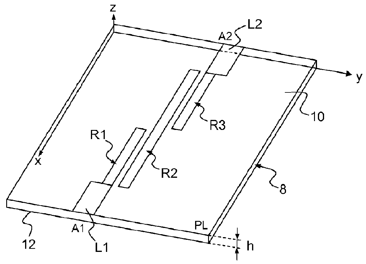
[0073]FIG. 4a, shows an adjustable filter according to the invention having the same structure as the filter of FIG. 1.

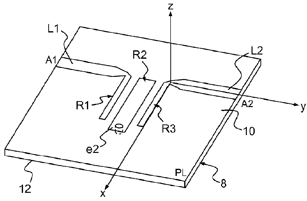
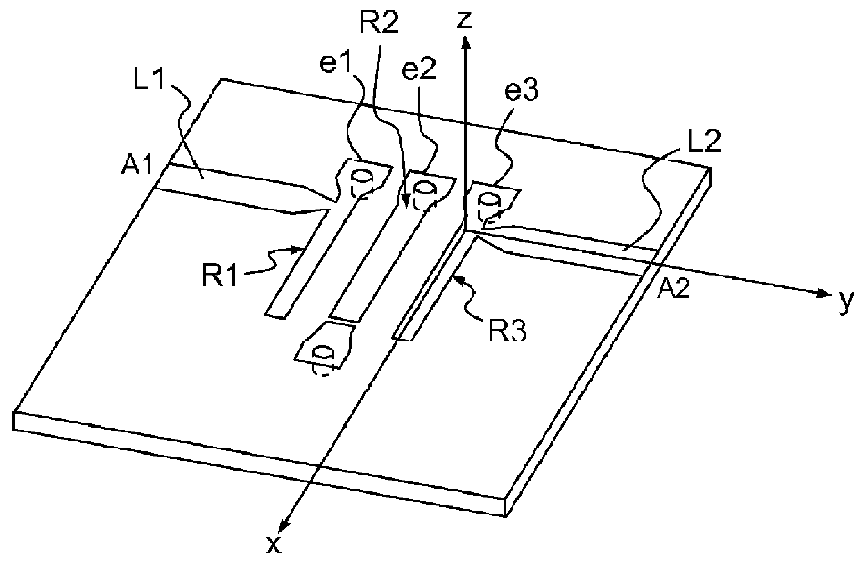
[0074]The filter of FIG. 4a according to the invention comprises a half-wave resonator R2 coupled in parallel over half its length with two adjacent quarter-wave resonators, a resonator R1 linked by the line L1 to the port A1 of the filter and a resonator R3 linked by the line L2 to the port A2 of the filter. The three resonator R1, R2, R3 are produced in the form of microstrip lines on a dielectric substrate of thickness h.

[0075]According to a principal characteristic of the planar filter according to the invention the resonator R1 and the resonator R3 each comprise two segments t1, t2 of microstrip transmission lines of like characteristic impedance Zc and widths W, two segments of one and the same resonator being linked by a respective...


PUM


Abstract

An adjustable radiofrequency filter in planar technology comprises at least one dielectric substrate and n resonators R1, R2, . . . Ri, . . . Rj, . . . Rk, . . . Rn integrated into the substrate, and each resonator comprises, on a principal plane PL of the substrate, a succession of segments t1, t2, . . . tq, . . . tp of planar transmission lines each having two ends, p being the number of segments of planar transmission lines of the resonator Ri considered, p being equal to or greater than 2, q being the rank of the segment, an end of a segment tq of a resonator Ri being opposite and separated by a distance d from an end of the next segment t(q+1) of the same resonator Ri, the opposite ends of the successive segments of a resonator Rq being linked by an electrical link which locally raises the characteristic impedance of the resonator Ri considered.

Description

CROSS-REFERENCE TO RELATED APPLICATIONS[0001]This application is a National Stage of International patent application PCT / EP2012 / 052271, filed on Feb. 10, 2012, which claims priority to foreign French patent application No. FR 1100408, filed on Feb. 10, 2011, the disclosures of which are incorporated by reference in their entirety.FIELD OF THE INVENTION[0002]The invention relates to adjustable radiofrequency filters in planar technology that can be altered to obtain the desired filtering performance.BACKGROUND[0003]Certain types of radiofrequency (RF) filters operating notably in high-frequency and microwave frequency bands comprise coupled resonators produced on the basis of transmission lines in planar technology.[0004]FIGS. 1, 2 and 3 respectively represent three bandpass planar filters of the prior art.[0005]FIG. 1 represents a planar technology filter reduced to its simplest expression. This filter comprises a half-wave resonator R2 coupled in parallel over half its length with...

Claims


Application Information

Patent Timeline
IPC IPC(8): H01P1/203H01P5/02
CPCH01P1/20327H01P1/20336H01P1/20363H01P1/20381H01P5/02
Inventor DENIS, STEPHANEHAQUET, GERARDCAZENAVE, JEAN-PIERRE
Owner THALES SA
Why Eureka
Try Eureka