Digital printing process

a printing process and digital technology, applied in printing, duplicating/marking methods, printing blankets, etc., can solve the problems of hydrophobic outer surface or release layer however undesirabl

Active Publication Date: 2016-07-05
LANDA
View PDF210 Cites 37 Cited by
  • Summary
  • Abstract
  • Description
  • Claims
  • Application Information

AI Technical Summary

Benefits of technology

[0013]There is disclosed here a printing process which comprises directing droplets of an ink onto an intermediate transfer member to form an ink image, the ink including an organic polymeric resin and a coloring agent in an aqueous carrier, and the transfer member having a hydrophobic outer surface, each ink droplet in the ink image spreading on impinging upon the intermediate transfer member to form an ink film; drying the ink while the ink image is being transported by the intermediate transfer member by evaporating the aqueous carrier from the ink image to leave a residue film of resin and coloring agent; and transferring the residue film to a substrate, wherein the chemical compositions of the ink and of the surface of the intermediate transfer member are selected such that attractive intermolecular forces between molecules in the outer skin of each droplet and on the surface of the intermediate transfer member counteract the tendency of the ink film produced by each droplet to bead under the action of the surface tension of the aqueous carrier, without causing each droplet to spread by wetting the surface of the intermediate transfer member.

Problems solved by technology

Such a hydrophobic outer surface or release layer is however undesirable during ink image formation because bead-like ink droplets cannot be stably transported by a fast moving intermediate transfer member and because they result in a thicker film with less coverage of the surface of the substrate.

Method used


Image

  • Digital printing process
  • Digital printing process
  • Digital printing process

Examples


Embodiment Construction

General Overview

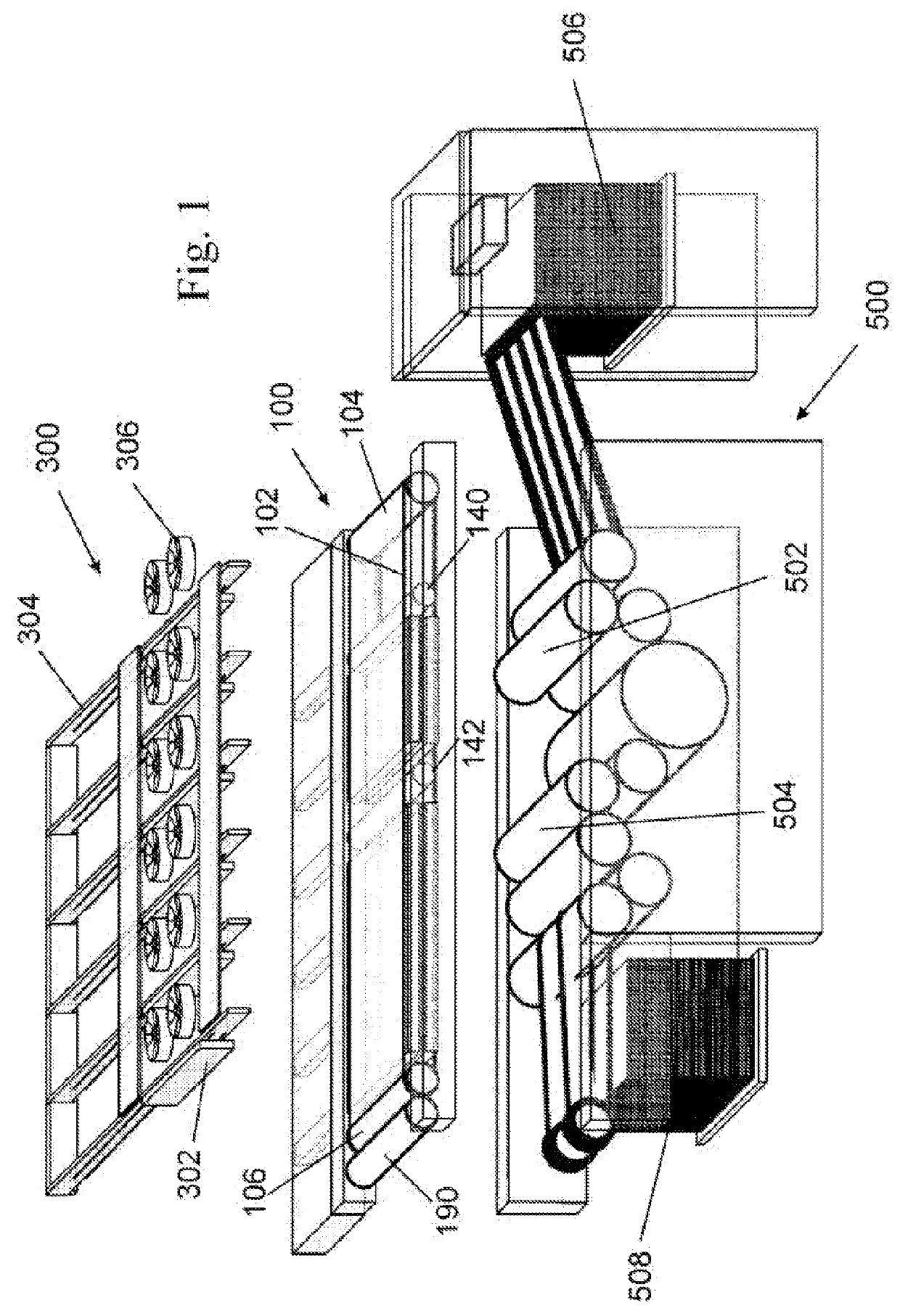
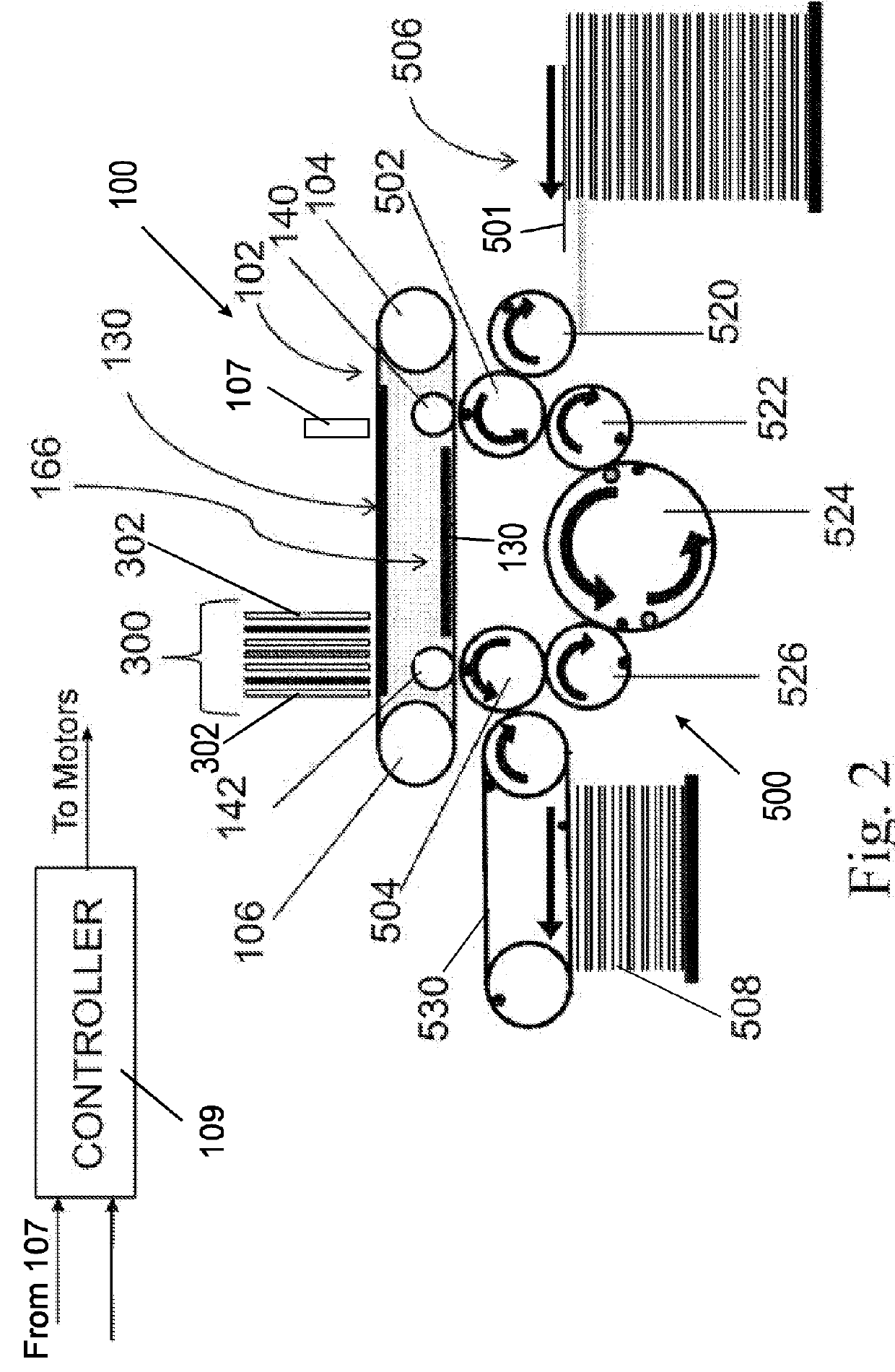
[0065]The printer shown in FIGS. 1 and 2 essentially comprises three separate and mutually interacting systems, namely a blanket system 100, an image forming system 300 above the blanket system 100 and a substrate transport system 500 below the blanket system 100.

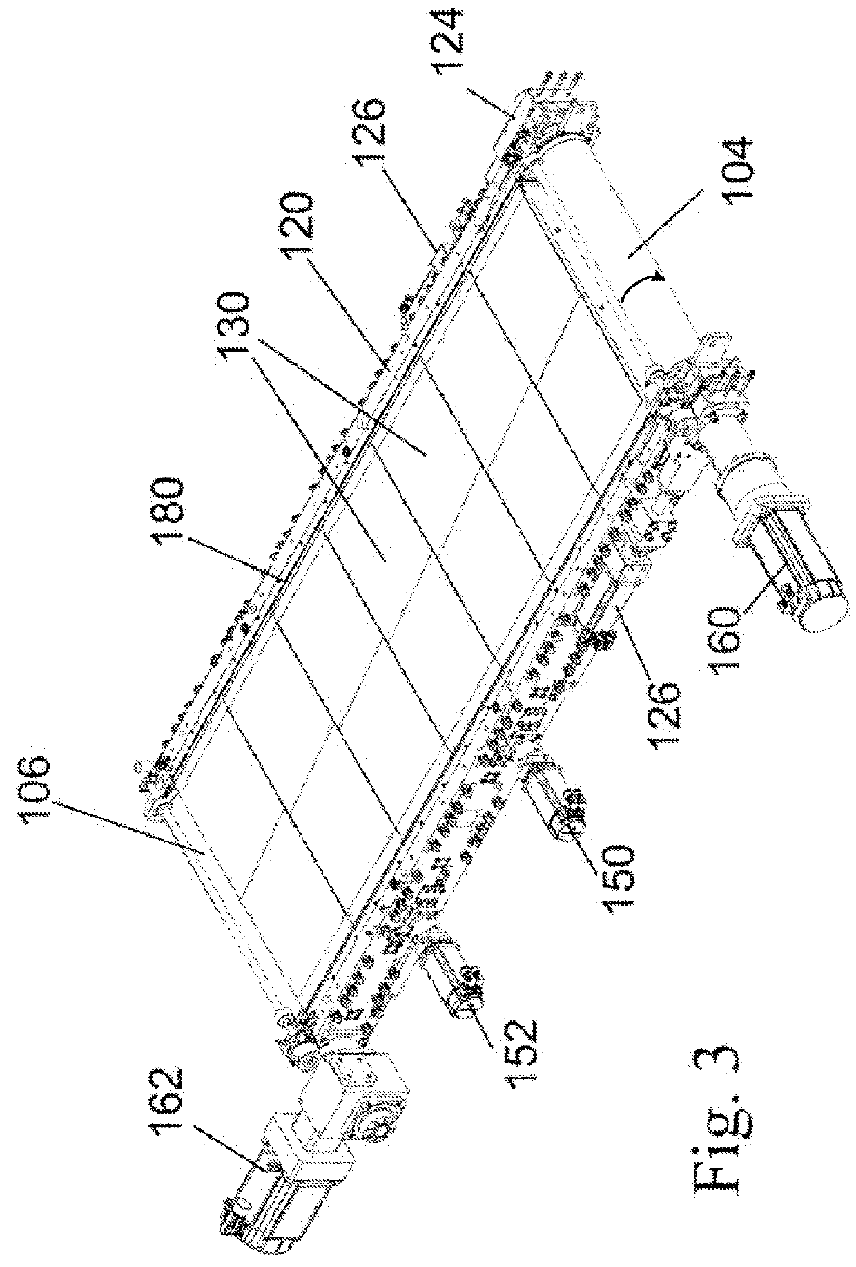
[0066]The blanket system 100 comprises an endless belt or blanket 102 that acts as an intermediate transfer member and is guided over two rollers 104, 106. An image made up of dots of an aqueous ink is applied by image forming system 300 to an upper run of blanket 102 at a location referred herein as the image forming station. A lower run selectively interacts at two impression stations with two impression cylinders 502 and 504 of the substrate transport system 500 to impress an image onto a substrate compressed between the blanket 102 and the respective impression cylinder 502, 504 by the action of respective pressure or nip rollers 140, 142. As will be explained below, the purpose of there being two impres...


PUM

PropertyMeasurementUnit
particle size D50aaaaaaaaaa

Abstract

A printing process is disclosed which comprises directing droplets of an ink onto an intermediate transfer member to form an ink image, the ink including an organic polymeric resin and a coloring agent in an aqueous carrier, and the transfer member having a hydrophobic outer surface so that each ink droplet in the ink image spreads on impinging upon the intermediate transfer member to form an ink film. The ink is dried while the ink image is being transported by the intermediate transfer member by evaporating the aqueous carrier from the ink image to leave a residue film of resin and coloring agent. The residue film is then transferred to a substrate. The chemical compositions of the ink and of the surface of the intermediate transfer member are selected such that attractive intermolecular forces between molecules in the outer skin of each droplet and on the surface of the intermediate transfer member counteract the tendency of the ink film produced by each droplet to bead under the action of the surface tension of the aqueous carrier, without causing each droplet to spread by wetting the surface of the intermediate transfer member.

Description

CROSS-REFERENCE TO RELATED APPLICATIONS[0001]The present application is a National Phase of PCT Patent Application No. PCT / IB2013 / 051716 having International filing date of Mar. 5, 2013.FIELD OF THE INVENTION[0002]The present invention relates to a digital printing process.BACKGROUND[0003]Digital printing techniques have been developed that allow a printer to receive instructions directly from a computer without the need to prepare printing plates. Amongst these are color laser printers that use the xerographic process. Color laser printers using dry toners are suitable for certain applications, but they do not produce images of a photographic quality acceptable for publications, such as magazines.[0004]A process that is better suited for short run high quality digital printing is used in the HP-Indigo printer. In this process, an electrostatic image is produced on an electrically charged image bearing cylinder by exposure to laser light. The electrostatic charge attracts oil-based ...

Claims


Application Information

Patent Timeline
Patent Type & Authority Patents(United States)
IPC IPC(8): B41J11/00B41J2/01B41J2/005B41M5/025B41M5/03B41N10/00
CPCB41J2/0057B41M5/0256B41M5/03B41N10/00
Inventor LANDA, BENZIONSHEINMAN, YEHOSHUAABRAMOVICH, SAGIGOLODETZ, GALIANAKHMANOVICH, GREGORYSORIA, MEIR
Owner LANDA
Why Eureka
Try Eureka