Motor servo-drive for high performance motion control

a technology of high-performance motion control and servo motor, which is applied in the direction of electronic commutators, electric controllers, instruments, etc., can solve the problems of linear drives suffering from low efficiency, affecting the actual velocity, and limited correction of output current, so as to achieve maximum accuracy for commands

Inactive Publication Date: 2016-07-05
ACS MOTION CONTROL
View PDF1 Cites 3 Cited by
  • Summary
  • Abstract
  • Description
  • Claims
  • Application Information

AI Technical Summary

Benefits of technology

[0016]The current measurements carried out during the steady state phase by a sensor that is calibrated to cover the whole current range produces an electrical signal that represents the actual current, that is smaller than the electrical noise that is picked by the sensor and the measurement circuit. Embodiments of the present invention may thus use separate current sensors and measurement circuits, a first sensor and measurement circuit for measuring high currents (coarse measurement) and a second sensor and measurement circuit for measuring low currents (fine measurement) in order to obtain a combination of both large range of currents with the same signal to noise ratio and resolution as with the current art using a single sensor, and low level currents, with higher signal to noise ratio and higher resolution. The separate measurements improve position jitter and following errors. The result is a drive that provides improved velocity and positioning accuracy. When applying the present technique of coarse and fine measurements to a PWM drive, the PWM drive provides the same or better performance than an equivalent linear drive with a single current measurement sensor and it thereby allows the PWM drive to be used in place of a linear drive in a high current range, high accuracy application. Alternatively, the same technique of coarse and fine measurement may be applied to a linear drive to further improve its characteristics and thus achieve even better standstill jitter and following errors when compared to an equivalent linear drive with a single current measurement sensor.
[0044]the feature being a measurable feature having an operating range, the operating range comprising a relatively large range for transition states but remaining within a relatively smaller range for steady state operating of the actuator, the measurement device having a first, coarse, sensor optimized for measuring the relatively large range and a second, fine, sensor optimized for measuring the relatively smaller steady state range, thereby to maximize accuracy for the measurable feature during the steady state operation.

Problems solved by technology

It is well known that the correction to the output current is limited by the accuracy of the measurement and the extent that the current measured in fact represents the actual output.
Such deviations are typically due to quantization noise (or errors), electro-magnetic interference (EMI) from the surrounding electrical circuits and other sources of noise.
Any noise, say quantization noise, in the motor current may introduce noise into the force or torque that the motor produces and may thus negatively affect how well the actual velocity and the actual position follows the desired velocity and position.
It is well known that linear drives suffer from low efficiency relative to a PWM type of drive with the same output power capability, and therefore the linear drive dissipates a significant amount of heat by comparison.
The linear drives are relatively bigger and typically more expensive.
More particularly, existing PWM servo-drives are typically not used in applications that require jitter and following errors during standstill, of less than about 10 nanometers.
At constant velocity the following error that can be achieved with PWM drives is typically worse.

Method used


Image

  • Motor servo-drive for high performance motion control
  • Motor servo-drive for high performance motion control
  • Motor servo-drive for high performance motion control

Examples


Embodiment Construction

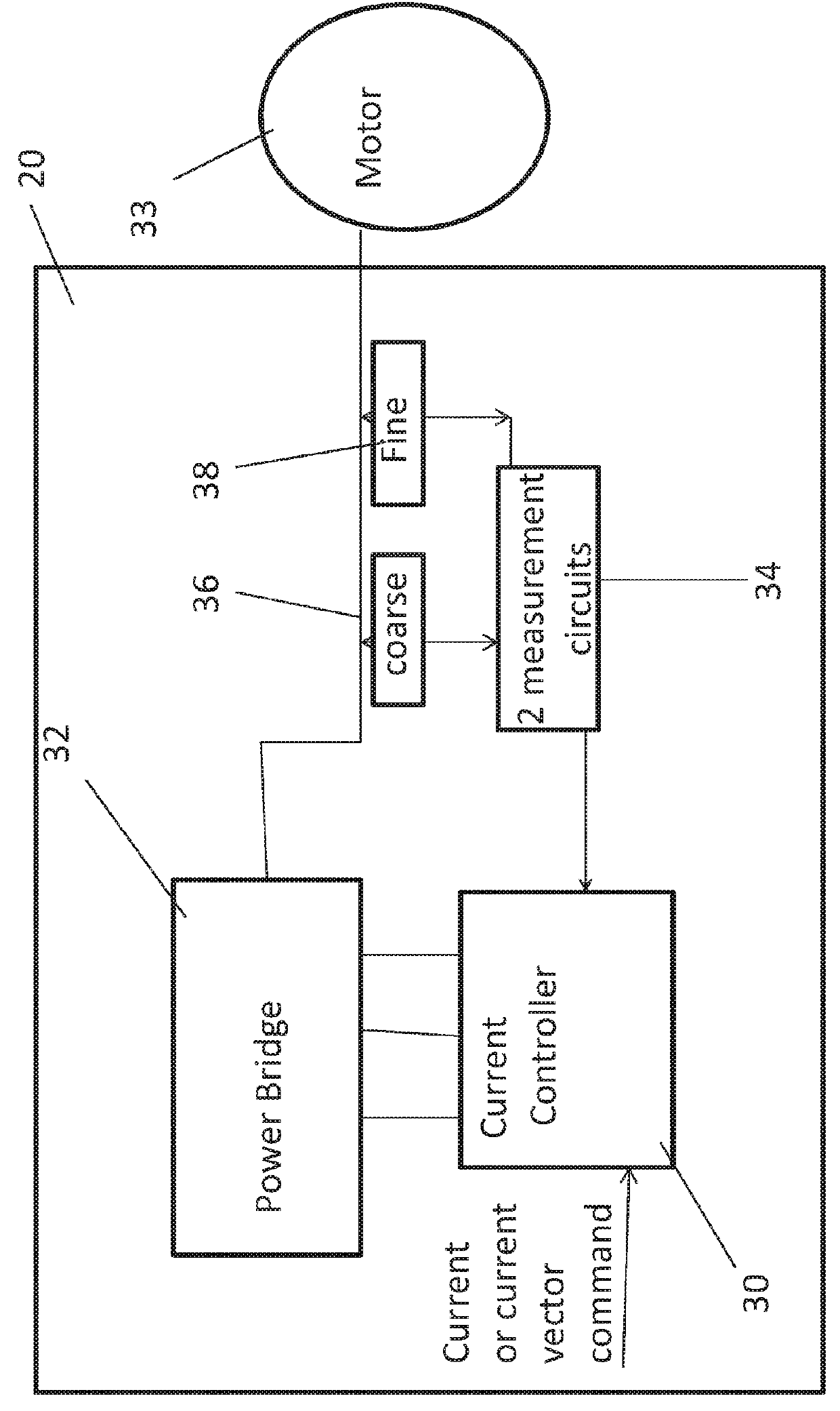
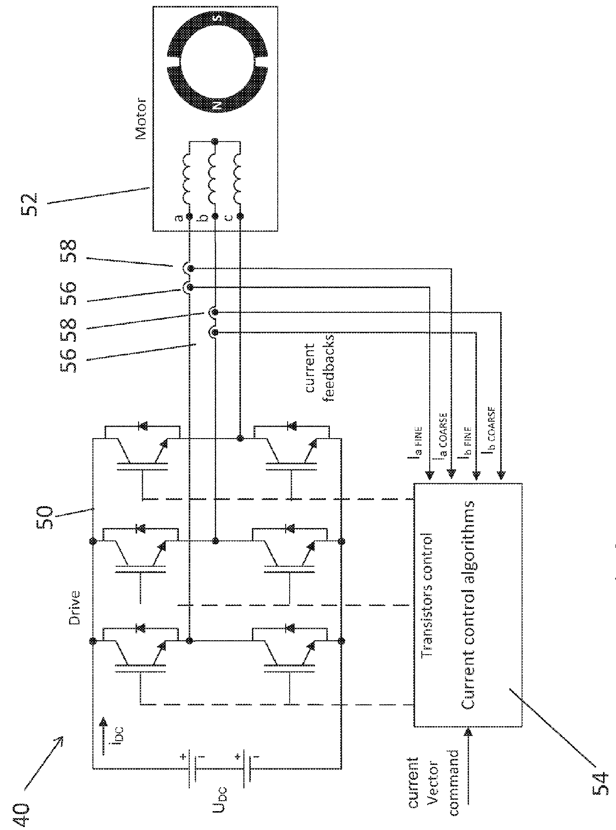
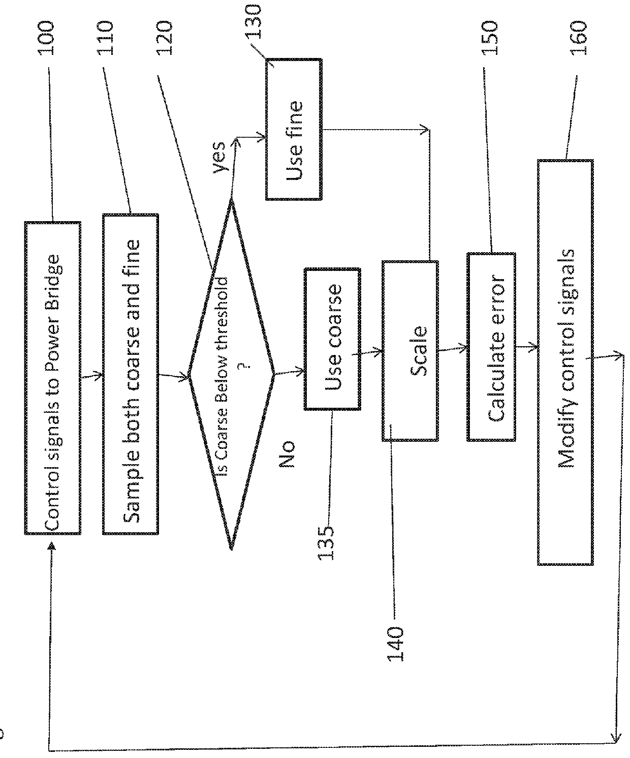
[0058]The present invention, in some embodiments thereof, relates to improving control of the motor current by implementing a method for measurements of the current of the motor over a wide current range. Sensitivity to noise may be improved over the current range, and specifically over low current levels, leading to better position and velocity control.

[0059]High performance velocity and position control systems utilize close loop feedback. The actual velocity and / or position may be measured and compared to the desired velocity and / or position. The deviation between the desired velocity or position and the actual measured velocity or position, the velocity or position error, is used to create a current command or a current command vector to the motor servo-drive, the drive command. As explained the servo-drive produces current that feeds the servo-motor, alternatively known as the motor current.

[0060]The present embodiments may improve measurements of the motor current, which enabl...


PUM


Abstract

A servo-drive system for feedback-based control of motion and positioning of a motor comprises a current measurement device that obtains a measure of current being drawn by the drive motor from which to provide feedback. The current has an operating range which is made up of a relatively large current range for acceleration but remains within a relatively smaller current range for steady state operating of the motor. The current measurement device has a first, coarse, sensor optimized for measuring the relatively large current range and a second, fine, sensor optimized for measuring the relatively smaller current range, thereby to maximize feedback accuracy during steady state operation.

Description

RELATED APPLICATION[0001]This application claims the benefit of priority of Israel Patent Application No. 235022 filed on Oct. 6, 2014, the contents of which are incorporated herein by reference in their entirety.FIELD AND BACKGROUND OF THE INVENTION[0002]The present invention, in some embodiments thereof, relates to improving the performance of motor servo-drives that feed servo-motors with current, and more particularly but not exclusively to improving current sensitivity across a whole current range, even if that range is large. The motor produces force (or torque) and acceleration that are directly related to the current. Better current enables more accurate velocity and position control of servo-motors. The more accurate the output current of the drive (that feeds the motor) follows the command; the more accurate is the velocity and position control of the drive. The improved performance of the drive is achieved by improving the signal to noise ratio of the current measurement ...

Claims


Application Information

Patent Timeline
Patent Type & Authority Patents(United States)
IPC IPC(8): G05F1/10H02P6/16G05B11/01G05B11/32
CPCG05B11/32G05B11/011H02P6/16
Inventor KIRSHENBOIM, ZE'EVKRAMER, BOAZKOGAN, VLADIMIR
Owner ACS MOTION CONTROL
Why Eureka
Try Eureka