Supercharge Your Innovation With Domain-Expert AI Agents!

Quad-array diode-less RF-to-DC rectifying charge-pump converter for energy harvesting

a charge-pump converter and diode-less rf-to-dc technology, applied in power conversion systems, electrical equipment without intermediate ac conversion, etc., can solve the problems of insufficient input sensitivity and power conversion efficiency for many applications, and insufficient sensitivity and power conversion efficiency of inputs for many applications

Active Publication Date: 2016-07-05
HONG KONG APPLIED SCI & TECH RES INST
View PDF13 Cites 3 Cited by
  • Summary
  • Abstract
  • Description
  • Claims
  • Application Information

AI Technical Summary

Benefits of technology

The patent text describes a new invention of a RF-to-DC converter circuit that is highly efficient and sensitive, allowing for the conversion of small voltages generated by RF waves that are not near-field. This invention is useful for low-power applications such as connected devices, where the distance between the RF source and the device is typically well beyond the near-field boundary. The technical effect of this invention is to provide a more efficient and sensitive energy-harvesting circuit for connected devices, allowing them to extract energy from external RF waves and recharge batteries.

Problems solved by technology

However, most connected devices are not placed so close to receivers.
Thus NFC power harvesting is not available for many connected devices since they are positioned too far from transmitters for near-field effects.
The distance from base station 142 to connected device 140 varies but is typically well beyond the near-field boundary, and far-field energy transfer is much less efficient and lossy than for near-field.
However, the input sensitivity and power conversion efficiency are insufficient for many applications.
Transistor threshold voltages may consume too much of the small available input signal from a tiny antenna.
Diodes or diode-connected transistors have too large of a voltage drop across them, thus consuming too much of the small input signal.

Method used


Image

  • Quad-array diode-less RF-to-DC rectifying charge-pump converter for energy harvesting
  • Quad-array diode-less RF-to-DC rectifying charge-pump converter for energy harvesting
  • Quad-array diode-less RF-to-DC rectifying charge-pump converter for energy harvesting

Examples


Embodiment Construction

[0023]The present invention relates to an improvement in RF-to-DC converters. The following description is presented to enable one of ordinary skill in the art to make and use the invention as provided in the context of a particular application and its requirements. Various modifications to the preferred embodiment will be apparent to those with skill in the art, and the general principles defined herein may be applied to other embodiments. Therefore, the present invention is not intended to be limited to the particular embodiments shown and described, but is to be accorded the widest scope consistent with the principles and novel features herein disclosed.

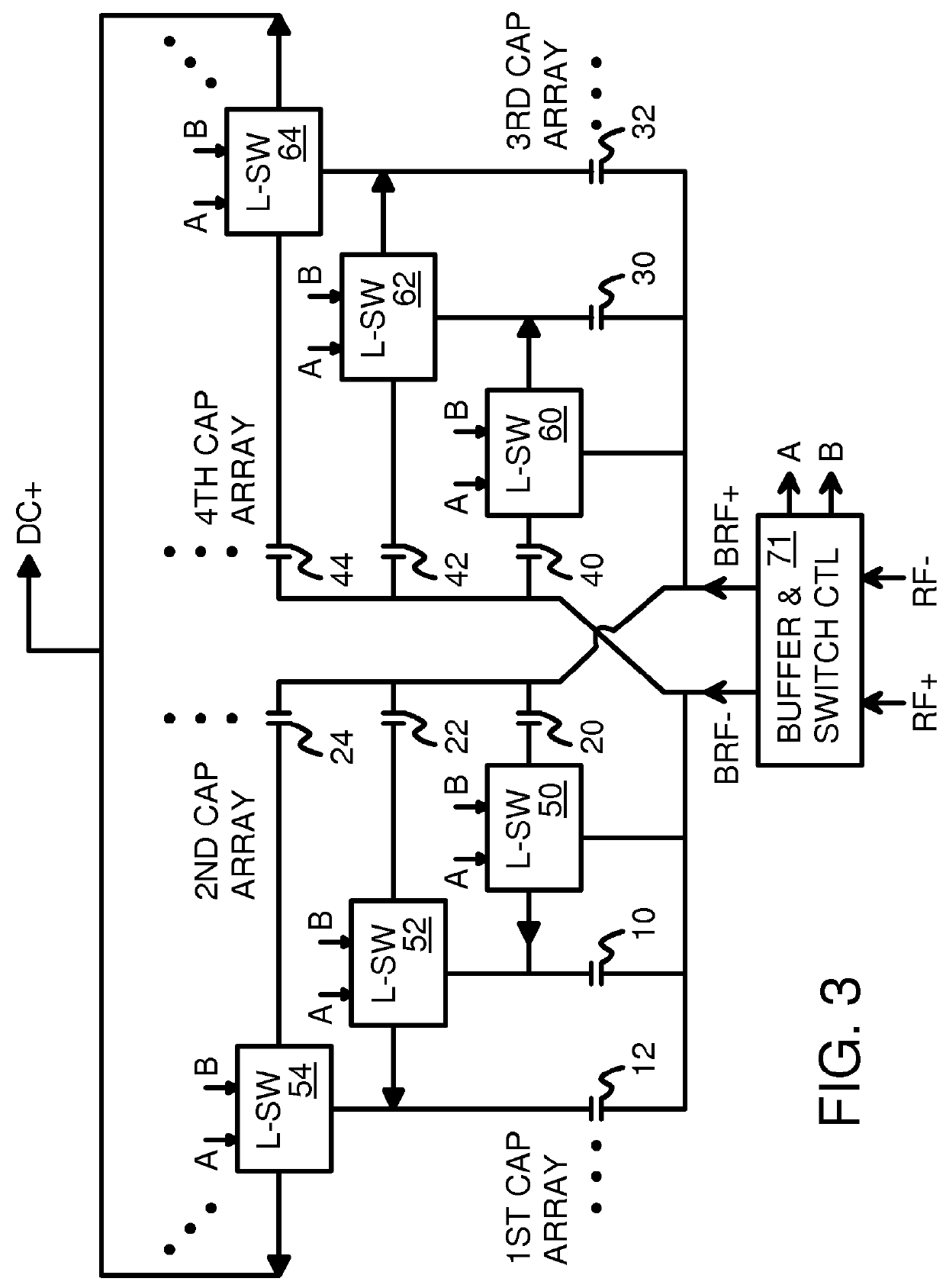
[0024]FIG. 3 is a diagram of a RF-to-DC converter using a dual-bank L-switch network with four capacitor arrays. An RF signal RF+, RF− is received from an antenna and converted to a DC output DC+ that can charge a capacitor or battery to harvest RF energy. The capacitor or battery can be connected between DC+ and a ground.

[0025]Bu...


PUM


Abstract

A RF-to-DC converter charges a battery or powers a circuit from the energy of received radio waves. The RF energy received is very small for far-field applications, so the converter is highly sensitive. Four capacitor arrays are arranged in two banks. Buffered RF signals pump bottom plates of the capacitors. A series of L-switches in each bank connect between the two capacitor arrays in that bank. Each L switch has a pre-charge switch that charges that stage's input capacitor, and a stage-transfer switch that shares charge from the input capacitor to an output capacitor for that stage. Switches in the two banks alternately pre-charge and pump, with the left bank pumping while the right bank pre-charges. Switches are transistors with substrates tied to their sources or actively driven by substrate control signals. One bank may use n-channel transistors with the other bank uses p-channel transistors. Gate voltages may be boosted.

Description

FIELD OF THE INVENTION[0001]This invention relates to Radio-Frequency (RF) to Direct Current (DC) conversion circuits, and more particularly to high-sensitivity energy harvesting circuits.BACKGROUND OF THE INVENTION[0002]Advances in semiconductor technology have allowed for increasingly sophisticated systems to be built in smaller packages. Small devices may contain circuitry to connect to the Internet and perform some useful function such as sensing temperature, heart rate, or acceleration, or controlling a camera, refrigerator, door lock, or automobile sub-system. A huge number of such connected devices will exist in the Internet of Things (IoT).[0003]Connections without wires (Wireless connections) are often preferred to connections with wires to minimize installation costs. Most of these connected devices will be battery powered, but some will derive energy from external electro-magnetic radiation (EM) such as radio waves. Energy harvesting circuits extract energy from an extern...

Claims


Application Information

Patent Timeline
Patent Type & Authority Patents(United States)
IPC IPC(8): H02M3/07H02M7/217
CPCH02M7/217H02M3/07H02M7/103
Inventor KWONG, KWOK KUEN DAVIDLAI, YAT TUNGKWOK, KA HUNG
Owner HONG KONG APPLIED SCI & TECH RES INST
Features
  • R&D
  • Intellectual Property
  • Life Sciences
  • Materials
  • Tech Scout
  • Unparalleled Data Quality
  • Higher Quality Content
  • 60% Fewer Hallucinations
Learn More