High pressure mechanical seal for cables and power lines in oil wells

a technology of mechanical sealing and power lines, which is applied in the direction of sealing/packing, earth-moving drilling, and well accessories, etc., can solve the problems of time of installation and adaptability, high cost of operator intervention, and inability to simultaneously and individually seal each of the lines

Active Publication Date: 2016-07-12
SOLPETROCOL
View PDF9 Cites 11 Cited by
  • Summary
  • Abstract
  • Description
  • Claims
  • Application Information

AI Technical Summary

Benefits of technology

[0024]The system is composed of four pieces. The adapter bushing which is coupled to the dangler of the production pipeline, the main sealing body which is coupled to a receptacle called seal seat, the sealing seat is housed inside the adapter bushing and the entire set comprises an upper cover called seal head which is coupled by thread to the adapter bushing. The resulting tightness from the pressure exerted by the sealing body prevents any fluid contained in the wellbore from leaking, whether such substances are liquid or gas, or any other element present inside the wellbore (annular space).

Problems solved by technology

The most common problems of the current technologies are the access for maintenance of the equipment, time of installation and adaptability to reduced and / or specific spaces.
In respect to the first problem, it generates a very expensive intervention by the operator of the wellbore, which requires a great logistic both in equipment and in staff to verify the functioning of the equipment.
Likewise, these systems do not allow to simultaneously and individually seal each of the lines entering the wellbore.
Currently, there is no device capable of simultaneously seal all the lines required to be installed inside an oil well.
In addition, there are several deficiencies in the installation, operation and uninstalling of the conventional sealing systems, due to some, such as QCI, use epoxy compounds as a base for the seal, which increases the installation time, does not guarantee tightness of the seal, and makes it impossible to reuse the equipment, given that the sealing effect of the epoxy is not reversible.
Other systems, such as BIW, use splices and interrupt the electrical fluid flow, generating thereby possible failure points, in addition to take 4 hours average for each of the splices made, if it is made under optimal environmental conditions.
All this represents high operation costs, in relation to additional working time, labor hours and machine hours employed, aside from the problems that may be consequently generated by the operative deficiencies.
At the moment of servicing (maintenance) or to perform an intervention on the wellbore, the conventional sealing systems cannot be inspected from the surface due to its installation is performed underneath the dangler of the production pipeline, whereby it is necessary to use an equipment for lifting the entire wellbore for lifting the production string, which corresponds to excessive not estimated costs, taking into account that it is not possible to predict the number of times a wellbore must be serviced during its working life.

Method used


Image

  • High pressure mechanical seal for cables and power lines in oil wells
  • High pressure mechanical seal for cables and power lines in oil wells
  • High pressure mechanical seal for cables and power lines in oil wells

Examples


Embodiment Construction

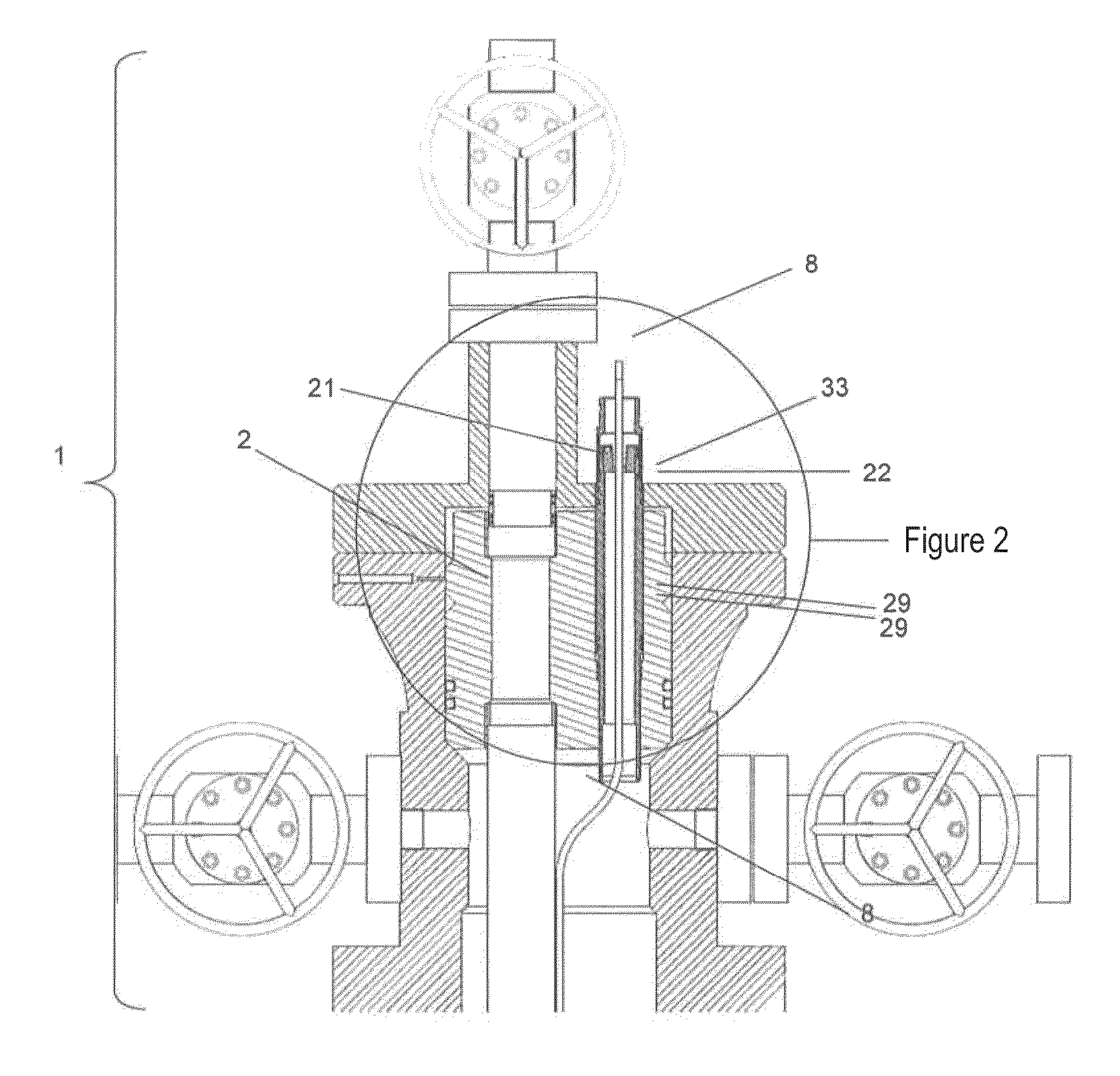
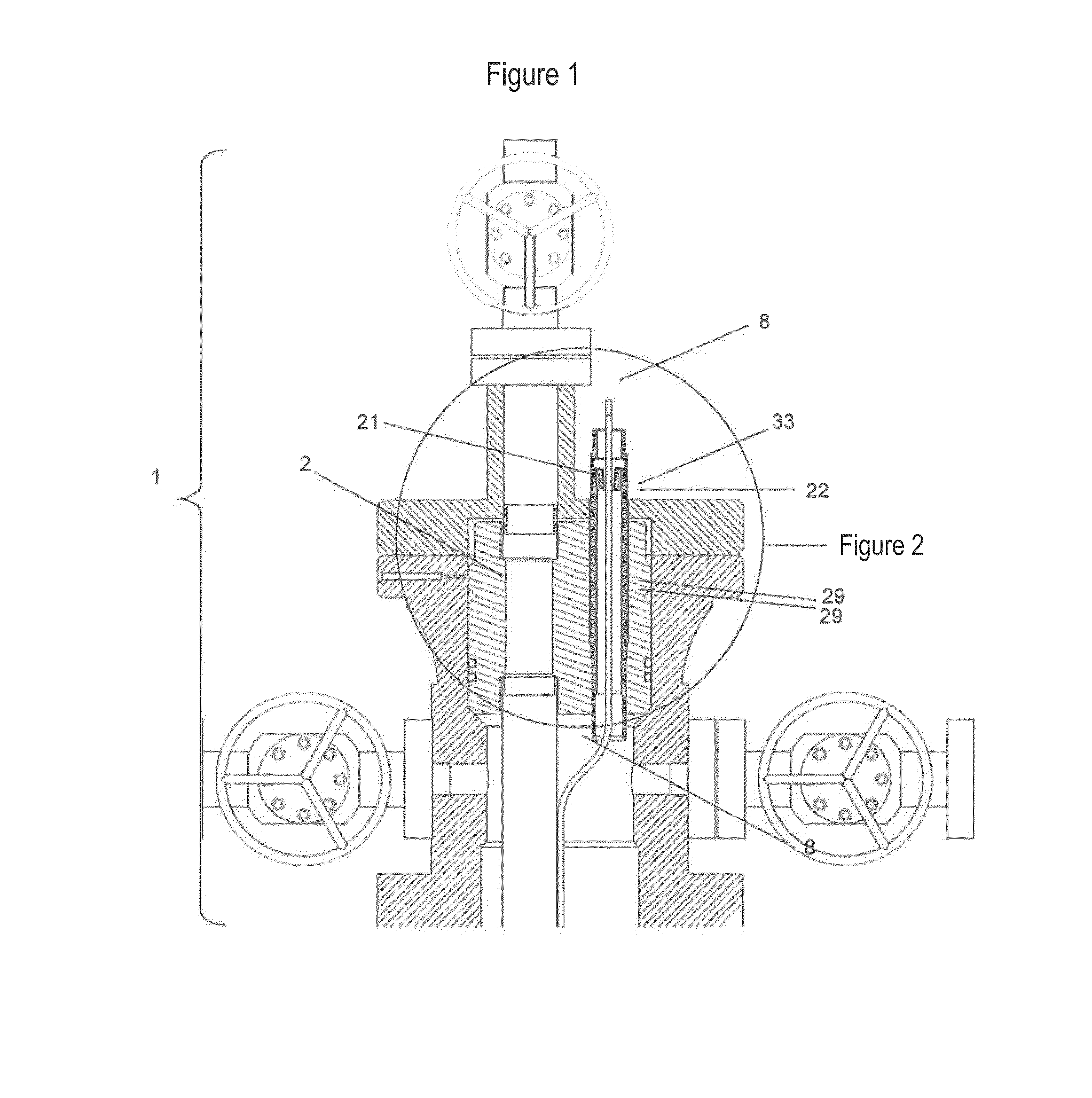
[0036]FIG. 1 shows a section of a well head (1) featuring a hole (21) through which the conduction line(s) pass, the dangler of the production pipeline (2) is disposed inside the head and it also features a hole (22) aligned with the hole (21) of the head. The contact zone (33) between the adapter bushing (4) and the well head (1) is sealed through two static joints (34).

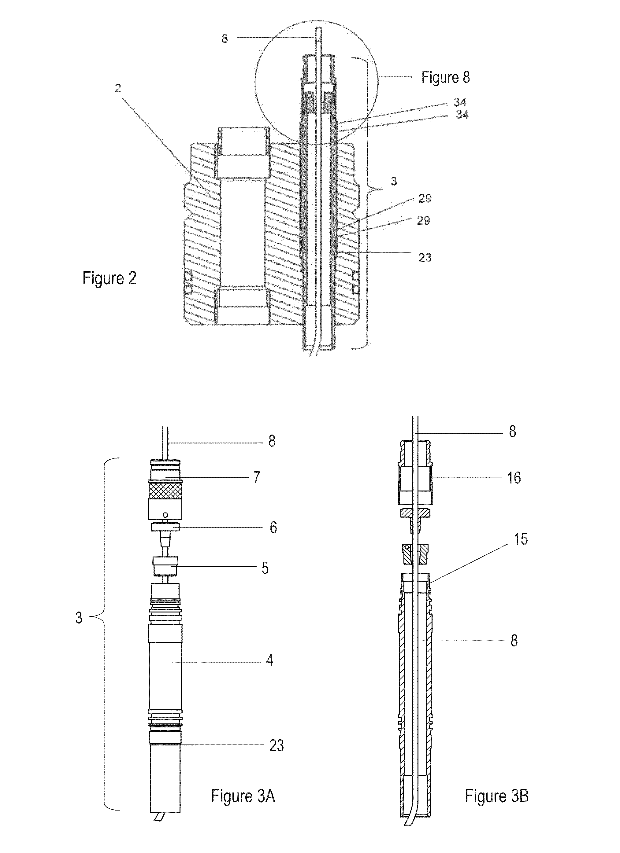
[0037]FIG. 2 shows an approach of FIG. 1, with the system of the present invention (3) assembled inside the dangler of the production pipeline (2), with a conduction line (8) passing through the entire system. The assembly is secured by means of the middle outer thread (23) of the adapter bushing (4). The contact zone between these two elements is sealed with two static joints (29) located in proximity to the middle outer thread (23) of the adapter bushing (4).

[0038]FIG. 3A shows the components of the system of the present invention (3) in its position and order of assembly, it is an exploded representation, and the...


PUM


Abstract

The present high pressure mechanical seal features a novel configuration capable of sealing from one up to simultaneously five power conduction lines, flow injection lines or control lines, in the same device. Adaptable to different configurations, types and size of conduction lines existing in the industry. The power conduction lines can be a cable of an electro-submersible pump or the cable in a down hole heater; the flow and control lines can be diluents injector capillaries or data and instrumentation cables or any other type of conduction line which can enter the inner atmosphere of the wellbore. Conduction lines are generally shaped as uniform cylindrical elements, which vary in diameter and material due to the cylindrical geometry, are adaptable to the sealing system of the present invention, such that the equipment can seal from only one line up to five lines depending on the requirement of the user.

Description

CROSS-REFERENCE TO RELATED APPLICATIONS[0001]This Application claims the priority of Colombian Patent Application No. CO-13-122315 filed on May 17, 2013, the contents of which is incorporated herein by reference in its entirety.[0002]The equipment object of the present invention is a high pressure mechanical seal which is installed in the head of oil wells. Its function is to allow the passage of lines, through the orifice in the dangler of the production pipe, located inside the head and to hermetically seal the inner atmosphere of the wellbore.BACKGROUND OF THE INVENTION[0003]The equipment object of the invention has its application in the oil industry, specifically in the field of gas and oil production, where it is necessary to pass lines through the head to downhole. The most commonly used lines are electrical cables and flow and control lines. The function of a line, depending on the structure, is to transport electrical power, fluids and information, from a source / receiver on...

Claims


Application Information

Patent Timeline
Patent Type & Authority Patents(United States)
IPC IPC(8): E21B33/03E21B33/04E21B33/038
CPCE21B33/0385F16L5/06
Inventor URREGO LOPERA, ALEJANDROOSPINA MEDINA, JUAN DAVID
Owner SOLPETROCOL
Why Eureka
Try Eureka