Tar removal device

a technology of tar removal device and tar filter, which is applied in the direction of lighting and heating apparatus, combustible gas purification/modification, combustion types, etc., can solve the problems of reducing blocking the function of the thermal apparatus, and achieves the effect of effective removal, simple device constitution and increased thermal efficiency

Active Publication Date: 2016-07-19
IHI CORP
View PDF12 Cites 1 Cited by
  • Summary
  • Abstract
  • Description
  • Claims
  • Application Information

AI Technical Summary

Benefits of technology

[0015]According to the tar removal device of the present invention, the tar contained in the gasification gas generated in the gasification furnace can be effectively removed by a simple device constitution. Further, heat of the combustion gas in which the tar is burnt can be effectively used to heat the circulating particles in the combustion furnace. As such, thermal efficiency is increased, and a gasification rate is improved.

Problems solved by technology

This tar adheres to piping or a thermal apparatus provided on a rear stage of the gasification furnace, thereby reducing the function of the thermal apparatus or causing blockage which stops the function of the thermal apparatus.

Method used


Image

  • Tar removal device
  • Tar removal device
  • Tar removal device

Examples


first embodiment

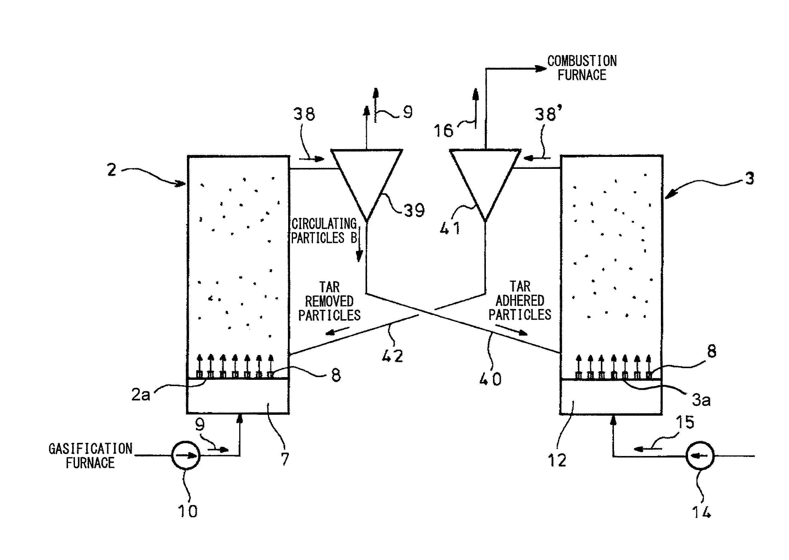
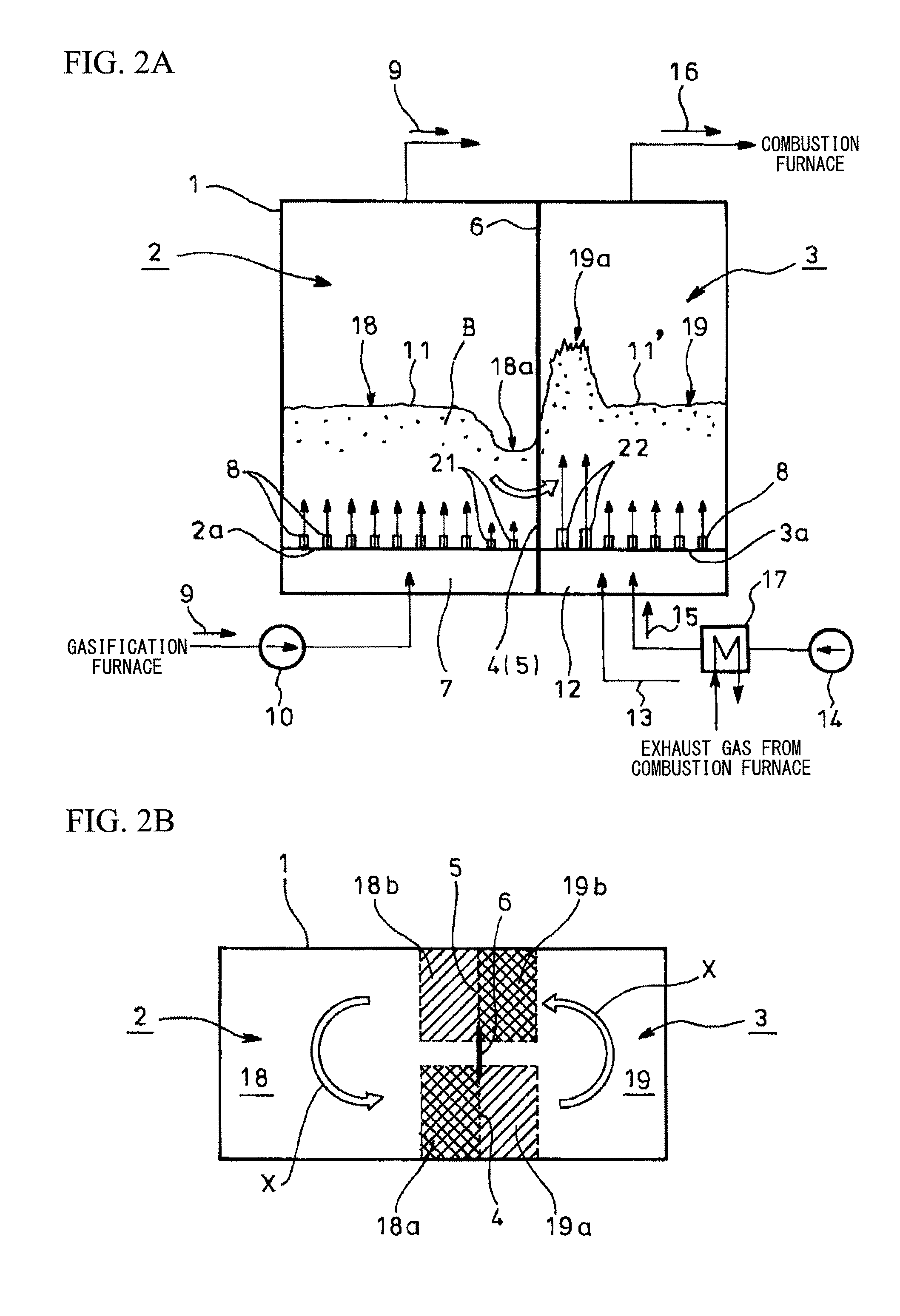
[0030]FIGS. 2A and 2B schematically show the tar removal device. The tar removal device includes the tar separation unit 2 and the tar combustion unit 3 on left and right sides in a container main body 1. A vertical partition wall 6 is provided at a middle position (facing position) between the tar separation unit 2 and the tar combustion unit 3 facing each other, and extends forward and backward in the center between the front and the rear (top and bottom in FIG. 2B). Front and rear passages 4 and 5 are defined between the container main body 1 and the vertical partition wall 6.

[0031]The tar separation unit 2 is provided with injection nozzles 8 on a bottom 2a thereof which communicate with an introduction chamber 7 formed at a lower portion thereof. The gasification gas 9 generated in the gasification furnace is increased in pressure by a pressurization fan 10 and is introduced into the introduction chamber 7, and the gasification gas 9 is ejected from the fluidizing injection noz...

third embodiment

[0050]FIG. 6 is a front view showing an outline of the tar removal device of the present invention which is similar to that of FIG. 5. In the embodiment of FIG. 6, a separate additional pressurization fan 34 is installed on a channel 33 branching off upstream from a pressurization fan 10. A gasification gas 9 of high pressure is directly guided from the additional pressurization fan 34 to a high-pressure introduction chamber 25, and a gasification gas 9 of medium pressure is directly guided from the pressurization fan 10 to a medium-pressure introduction chamber 23. Further, a gasification gas 9 of low pressure whose pressure is adjusted so as to be lower than that of the medium-pressure introduction chamber 23 by a second damper (pressure adjusting means) 35 is guided to a low-pressure introduction chamber 24.

[0051]Further, an additional air fan 36 is provided in addition to an air fan 14. Air 15 of high pressure is directly guided from the additional air fan 36 to a high-pressure ...


PUM

PropertyMeasurementUnit
cross-sectional aaaaaaaaaa
areaaaaaaaaaaa
cross-sectional areaaaaaaaaaaa

Abstract

A tar removal device removes tar contained in a gasification gas (9) generated in a gasification furnace of a two-towered gasifier having a combustion furnace (43) heating a heating medium (A) and the gasification furnace (47) introducing the heating medium (A) heated in the combustion furnace to perform gasification of a starting material (48). The tar removal device includes a tar separation unit (2) that introduces the gasification gas from the gasification furnace to fluidize the circulating particles (B) so as to adhere the tar in the gasification gas to the circulating particles, and a tar combustion unit (3) that introduces the circulating particles to which the tar is adhered at the tar separation unit, fluidizes the circulating particles using air (15) so as to burn the tar adhered to the circulating particles, supplies the combustion gas (16) in which the tar is burnt to the combustion furnace as a gas for combustion, and returns the circulating particles from which the tar is burnt and removed to the combustion furnace.

Description

TECHNICAL FIELD[0001]The present invention relates to a tar removal device for removing a tar contained in a gasification gas generated in a gasification furnace.[0002]Priority is claimed on Japanese Patent Application No. 2011-69742, filed on Mar. 28, 2011, the content of which is incorporated herein by reference.BACKGROUND ART[0003]Gasification systems are known in which solid fuels such as coal, organic wastes such as residues generated when petroleum is refined, waste plastics, sludge, municipal refuse, or biomass fuel are used as gasification starting materials. In the gasification systems, the starting materials are supplied to and gasified in a gasification furnace, such as a steam gasification furnace, a pyrolytic gasification furnace, or a partial oxidation gasification furnace, thereby generating gasification gas. A refined gas obtained by purifying and refining the gasification gas is supplied as either fuel for power-generating facilities, combustion furnaces, and intern...

Claims


Application Information

Patent Timeline
Patent Type & Authority Patents(United States)
IPC IPC(8): C10J3/58C10K1/30C10K1/26B01D49/00C10K3/00F23C10/10F23C10/00C10J3/48C10J3/56
CPCB01D49/00C10J3/482C10J3/56C10K1/26C10K1/30C10K3/003F23C10/002F23C10/10C10J2300/093C10J2300/0976C10J2300/0993C10J2300/1637C10J2300/1807C10J2300/1853
Inventor SUDA, TOSHIYUKI
Owner IHI CORP
Why Eureka
Try Eureka