Combined cycle power plant

a combined cycle power plant and active stack technology, applied in the direction of machines/engines, corrosion-reducing boiler components, lighting and heating apparatus, etc., can solve the problems of unavoidable performance reduction associated with recovery of less exhaust energy, and reduce thermal efficiency beyond what is required

Active Publication Date: 2016-08-02
GE INFRASTRUCTURE TECH INT LLC
View PDF30 Cites 4 Cited by
  • Summary
  • Abstract
  • Description
  • Claims
  • Application Information

AI Technical Summary

Problems solved by technology

For example, a higher HRSG exit gas temperature may be required in accordance with local regulations to allow for a lower cost (shorter) stack but can result in an unavoidable performance reduction associated with recovery of less exhaust energy.
Thus, at colder ambient temperatures, this recent arrangement would cause the HRSG exhaust gas temperature to tend to increase above the temperature requirement thus reducing thermal efficiency beyond what is required.

Method used


Image

  • Combined cycle power plant
  • Combined cycle power plant

Examples


Embodiment Construction

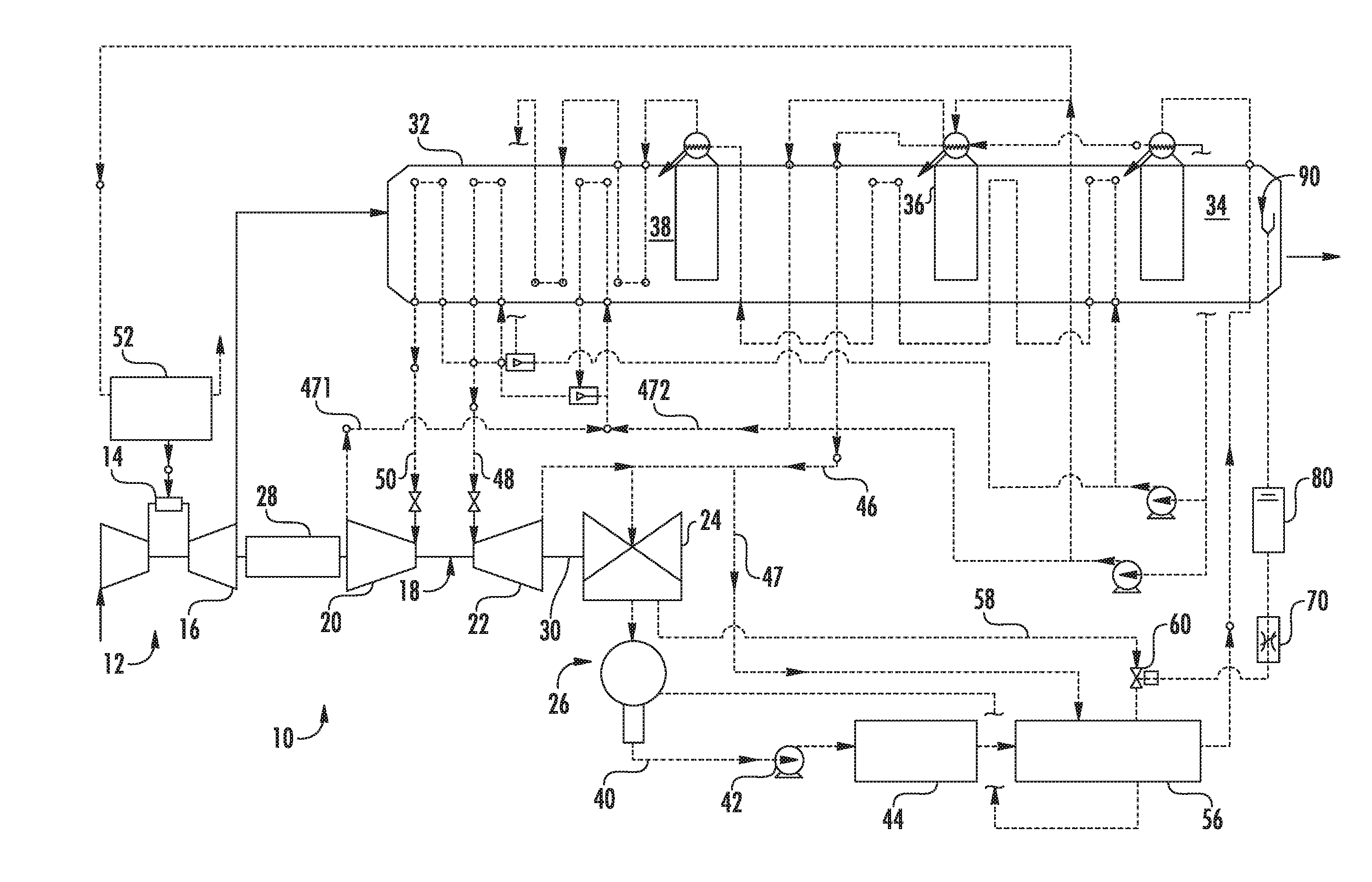
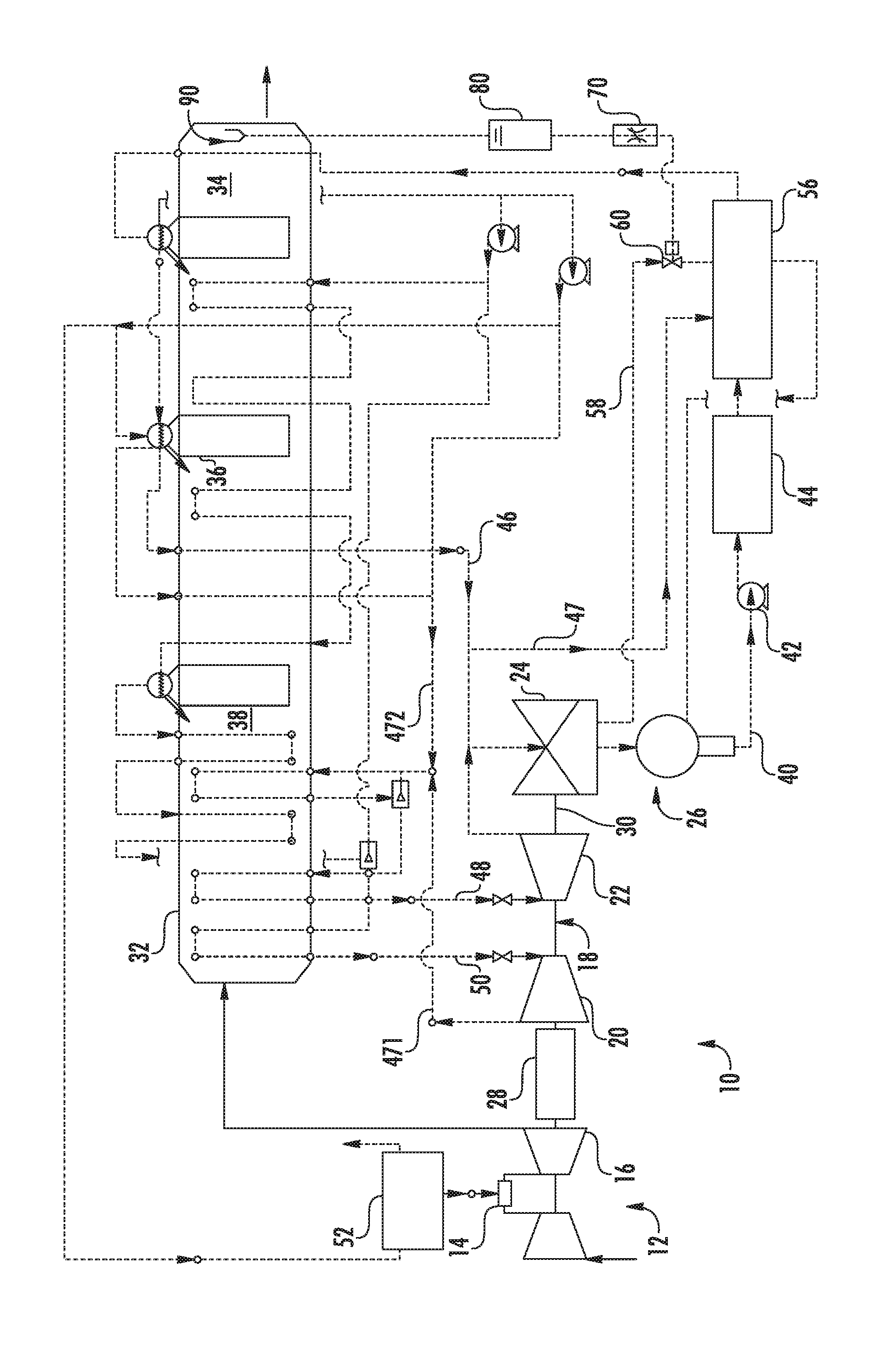
[0011]Referring now to the sole drawing, a combined cycle power plant 10 is provided. The power plant 10 includes a gas turbine engine system 12 with a combustion system 14 and a turbine section 16. The power plant 10 further includes a steam turbine engine system 18. The steam turbine engine system 18 includes a high pressure section 20, an intermediate pressure section 22 and one or more low pressure sections 24 with multiple steam admission points at the different pressures. The low pressure section 24 exhausts into a condenser 26. The steam turbine engine system 18 drives a generator 28 that produces electrical power. The gas turbine engine system 12, the steam turbine engine system 18 and the generator 28 may be arranged on a single shaft 30. Other configurations may be used.

[0012]The steam turbine engine system 18 is associated with a multi-pressure heat recovery steam generator (HRSG) 32. The HRSG 32 is a counter flow heat exchanger in which feedwater that passes through the ...


PUM


Abstract

A combined cycle power plant in which a gas turbine engine generates power, a heat recovery steam generator (HRSG) produces steam from high energy fluids produced from the generation of power in the gas turbine engine and a steam turbine engine generates additional power from the steam produced in the HRSG. The combined cycle power plant includes a heating element fluidly interposed between the steam turbine engine and the HRSG to heat fluid output from the steam turbine engine, which is to be fed to the HRSG and a control system to control an amount the fluid output from the steam turbine engine is heated by the heating element based on differences between HRSG and ambient temperatures.

Description

BACKGROUND OF THE INVENTION[0001]The subject matter disclosed herein relates to active stack temperature management via controlled steam extracted in a combined cycle power plant.[0002]A combined cycle power plant utilizes a gas turbine engine and a steam turbine engine in combination to produce power. The power plant is arranged such that the gas turbine engine is thermally connected to the steam turbine engine through a heat recovery steam generator (“HRSG”). The HRSG is a non-contact heat exchanger that allows feedwater for the steam generation process to be heated by otherwise wasted gas turbine engine exhaust gases. The HRSG is a large duct with tube bundles interposed therein such that water is heated to steam as the exhaust gases pass through the duct.[0003]Modern combined cycles typically employ two (2) or three (3) steam generation pressures to recover energy from the gas turbine engine exhaust. These cycles also often include water supply temperature controls to maintain t...

Claims


Application Information

Patent Timeline
Patent Type & Authority Patents(United States)
IPC IPC(8): F01K13/02F01K23/10F22B37/02
CPCF01K13/02F01K23/10F01K23/108F22B37/025Y02E20/16
Inventor PANG, RAYMONDSMITH, RAUB WARFIELD
Owner GE INFRASTRUCTURE TECH INT LLC
Why Eureka
Try Eureka