Joint seal system

a seal system and joint technology, applied in the field of joint seal systems, can solve the problems of sealing system failure, thick and inflexible seals, and joints that are subject to damage,

Active Publication Date: 2016-08-02
SCHUL INT COMPANY
View PDF83 Cites 74 Cited by
  • Summary
  • Abstract
  • Description
  • Claims
  • Application Information

AI Technical Summary

Benefits of technology

[0022]The present invention thus provides redundancy, and potentially a status notification of change

Problems solved by technology

Moreover, these joints are subject to damage over time.
Most damage is from vandalism, wear, and environmental factors, where the seal may become thick and inflexible or are fragile.
These systems, however, often fail due to the differences in compression and expansion of the various constituents, or the lack of bonding between layers, or because the system is directed to a particular purpose, such as water-resistance, but is exposed to fire, causing the seal system to fail and permit water to migrate behind the seal system.
Vandalism, normal wear and environmental exposure can change or defeat the properties of the exposed surface coating or membrane.
There is also the case where the best material or barrier may not be used because it is aesthetically unpleasing or cannot easily be colored.
Additionally, in some cases the movement of the joint may be limited, sometimes to only twenty-five percent (+/−25%) in compression and expansion, for a total movement of only fifty percent (50%).
Additionally, for joints greater than the one (1) inch size, typically of pre-compressed joint sealants with a silicone face, a myriad of potential failure risks exist.
Typically the surface coatin

Method used


Image

  • Joint seal system
  • Joint seal system
  • Joint seal system

Examples


first embodiment

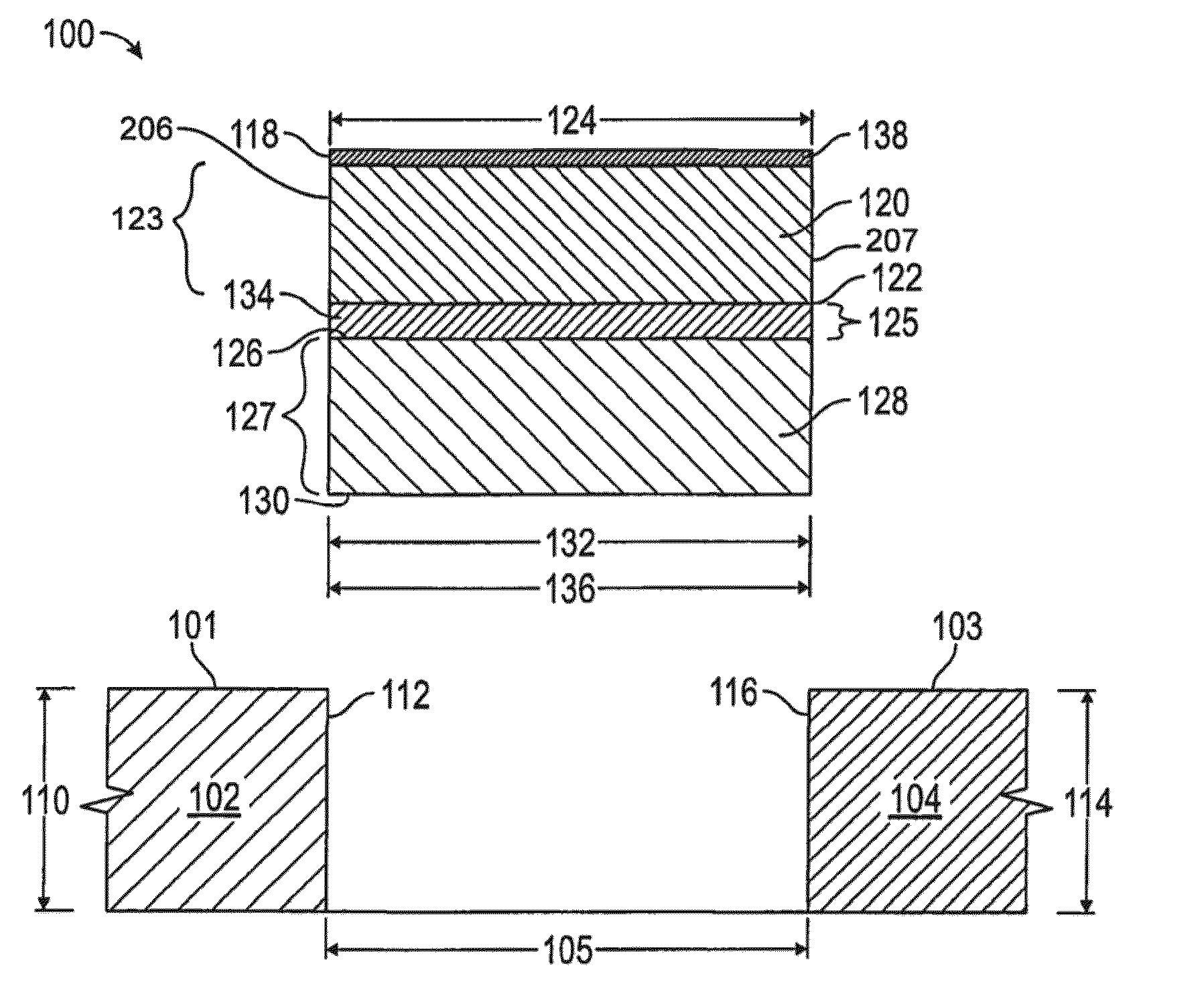
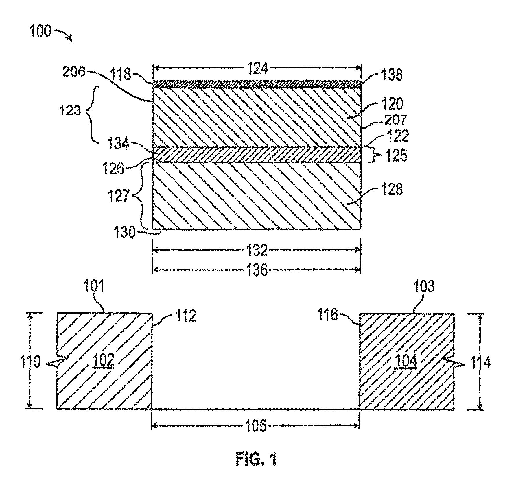
[0050]The joint seal 100 may further include an elastomer 138, such as silicone, adhered to the first body top 118 and / or to the bottom of the bottom-most layer, the second body bottom 130 in the

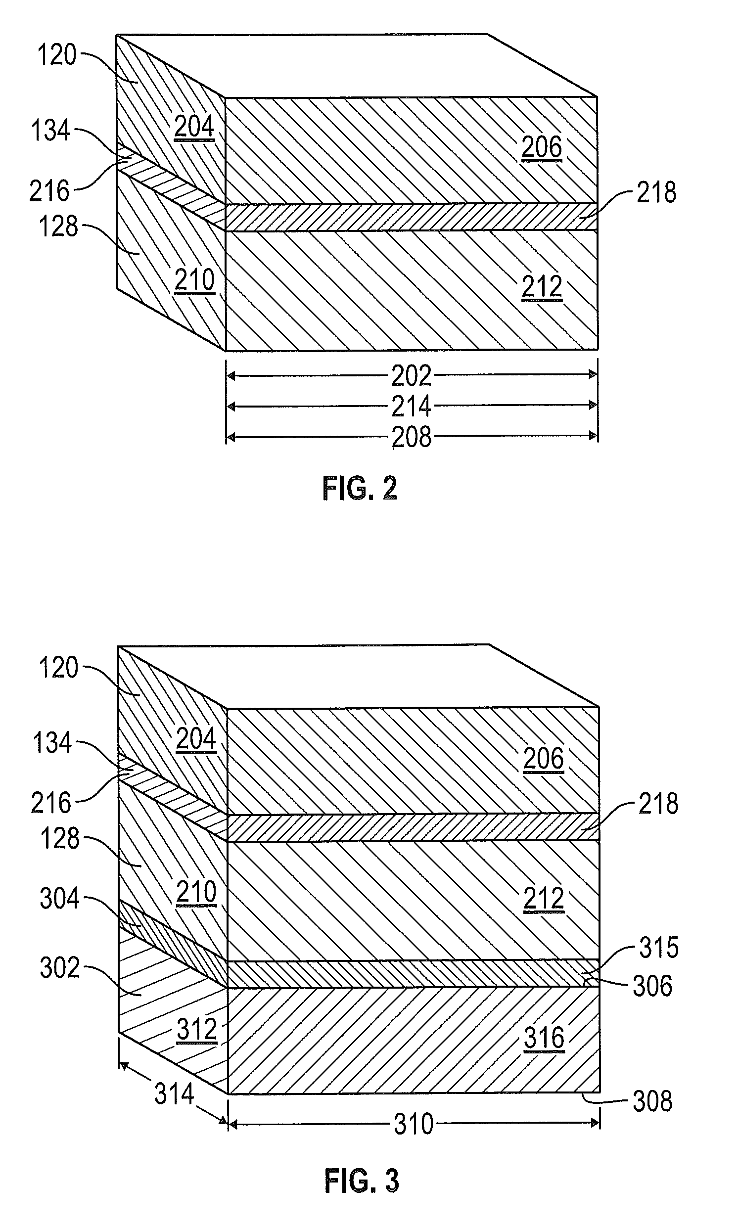
[0051]Referring now to FIG. 3, in another embodiment, the joint seal 100 may further include a third body of compressible foam 302 and a second barrier 304. In this embodiment, the third body of compressible foam 302 includes a third body top 306, a third body bottom 308, a third body length 310, a third body first end 312, a third body width 314, and a third body first side 316. The first body length 202 and the third body length 310 are equivalent, and the first body width 124 and the third body width 314 are equivalent. In this embodiment, the second barrier 304 is adhered to the second body of compressible foam 128 at the second body bottom 130 and is adhered to the third body of compressible foam 302 at the third body top 306. The second barrier 304 would include a layer of a heat barri...

embodiment 400

[0057]Referring now to FIG. 4, in an alternative embodiment 400, the joint seal includes a first body of compressible foam 120, a second body of compressible foam 128, and a barrier 134 adhered to both the first body of compressible foam 120 and the second body of compressible foam 128, wherein the compressible bodies have equivalent lengths and widths but the barrier extends beyond the edge of the first body of compressible foam 120 on at least one side to provide a wing 402 can be turned up (or down) and adhered, at installation, to the substrate 102, 104. Additionally, a slow drying adhesive may be applied to the wing 402 before insertion. Traditional, faster drying adhesive, such as epoxy, are to be avoided as they can cure before insertion.

[0058]This embodiment allows the barrier 134 to extend past the compressible body laminations and be used as wing 402 to be set into the concrete substrate 102 or polymer nosing 804, as illustrated in FIG. 8. This is helpful for split face co...

embodiment 700

[0061]Referring now to FIG. 7, in another further alternative embodiment 700, the barrier 134 may be of a narrower width than the first body 120 and the second body 128. Thus, the barrier 134 may terminate short of the edge of the first body 120 and the second body 128. This variation allows for the benefit of the different foams for the first body 120 and the second body 128 and also allows for the barrier 134 to accept less compression while still providing its intended properties.

[0062]In connection with each embodiment, cutting the first body 120 and the second body 128 into interlocking (male / female) sections using a radius of at least 0.1875 inches permits a thicker barrier 134 to be used without bowing or deformation of the foam, a benefit previously available only when a thin barrier 134 might be used. In the prior art, use of a random accordion style would cause the barrier 134 to fatigue after cycling.

[0063]An example is a joint seal using two different fire-rated foams as...


PUM

PropertyMeasurementUnit
Distanceaaaaaaaaaa
Lengthaaaaaaaaaa
Thicknessaaaaaaaaaa

Abstract

An integral multilayer joint seal system. Layers of foam, layered co-planar to the adjacent surface, are interspersed with a barrier layer. The foam layers may be uncompressed or partially compressed at the time of joint formation and may be composed of open or closed, or hybrid, cell foam. The foam may be impregnated with a fire retardant or may be composed of a fire retardant material, if desired. The barrier may have a tensile strength greater than the adjacent foam and may be different in dimensions from the layers of foam. The joint may have an elastomer, such as silicone, at its top and/or bottom, and may even include an elastomer layer within or about the barrier.

Description

CROSS-REFERENCE TO RELATED APPLICATIONS[0001]The priority of U.S. Provisional Patent Application No. 61 / 946,311, filed Feb. 28, 2014 for “Joint Seal System,” is hereby claimed and the specification thereof is incorporated herein by reference.STATEMENT REGARDING FEDERALLY SPONSORED RESEARCH OR DEVELOPMENT[0002]Not Applicable.BACKGROUND[0003]1. Field[0004]The present disclosure relates generally to systems for creating a durable seal between adjacent panels, including those which may be subject to temperature expansion and contraction or mechanical shear. More particularly, the present disclosure is directed to providing an integral multilayer joint seal system against one or more of water, fire, sound, air, smell, radiation, resistant and / or heat.[0005]2. Description of the Related Art[0006]Construction panels come in many different sizes and shapes and may be used for various purposes, including roadways, sideways, and pre-cast structures, particularly buildings. Use of precast conc...

Claims


Application Information

Patent Timeline
IPC IPC(8): F16J15/10B32B38/00B32B37/16F16J15/06B32B5/32B32B3/02B32B7/12B32B15/04B32B37/02
CPCF16J15/104F16J15/108F16J15/065B32B37/16B32B37/02B32B38/0004B32B5/32B32B3/02B32B7/12B32B15/046B32B2305/022B32B2307/20B32B2307/7242B32B2307/7246B32B2307/7265B32B2307/54B32B2307/3065B32B2581/00B32B2255/102B32B7/02B32B15/20B32B25/045B32B25/20B32B27/065B32B2260/02B32B2266/06B32B2266/08B32B2274/00B32B2457/00B32B2607/00B32B5/18B32B2266/0278B32B2307/202B32B2307/302B32B2307/304B32B2307/51B32B2307/728B32B2307/73B32B2419/00
Inventor ROBINSON, STEVEN R.
Owner SCHUL INT COMPANY
Why Eureka
Try Eureka