Binary power generation system

a power generation system and power generation technology, applied in the field ofbinary power generation systems, can solve the problems of low power generation efficiency, high construction cost, and low efficiency of new thermal power plants and the like, and achieve the effects of high enthalpy, high proportion of flashing steam, and high enthalpy

Active Publication Date: 2016-08-09
KK TOSHIBA
View PDF29 Cites 2 Cited by
  • Summary
  • Abstract
  • Description
  • Claims
  • Application Information

AI Technical Summary

Benefits of technology

[0021]As described above, demand for geothermal power generation has been increasing from the viewpoint of global warming. Power plants have already been constructed in locations where high quality geothermal sources are and in locations where geothermal sources have high enthalpy and provide a high proportion of flashed steam when reduced in pressure. On existing geothermal power plants, it is reported that the heat sources in the entire locations are weakening, and the proportion of steam is on the decrease and the proportion of hot water on the increase. Under the circumstances, a binary geothermal power generation system using not a steam turbine but a low-boiling working medium such as an organic medium is advantageous. Since geothermal sources are seldom fully depleted of steam to produce only hot water, a power generation system combining a flash type and a binary type is the most advantageous.
[0022]Among the foregoing systems combining a flash geothermal power generation system and a binary geothermal power generation system are ones that reduce the pressure of (flash) the geothermal source before using only the hot water for binary power generation, and ones that use both the exhaust of the turbine driven by the flashed steam and the hot water for binary power generation. The binary power generation systems that perform binary power generation by using only the hot water as a heat source have a small capacity, a low output rate, and a high unit cost of binary power generation.
[0023]Assume a system in which a turbine driven by flashed steam has a back pressure higher than or equal to atmospheric pressure. The latent heat of the steam of 100 degrees centigrade or above evaporates a working medium such as an organic medium. The vapor medium is superheated by hot water from the outlet of a pressure reducing steam-liquid separator, having a temperature higher than that of the exhausted turbine steam, and drives a medium turbine. The system includes a regenerator that performs heat exchange between the superheated vapor from the outlet of the medium turbine and liquid medium from a condenser. In such a system, the heat exchange is performed between the vapor medium from the turbine outlet, which originally has a high degree of superheat, and the liquid medium. This increases pressure loss on the vapor medium side of the regenerator and increases the outlet pressure of the medium turbine, failing to provide a high effect. In addition, the exhaust gas of the steam turbine originally contains noncondensable gas, which needs to be extracted and collected.
[0024]Embodiments of the present invention have been achieved in view of the foregoing circumstances, and it is an object thereof to increase the efficiency of a binary power generation system that combines a geothermal flash vapor cycle and a non-water working medium cycle.Means for Solving the Problems

Problems solved by technology

As a result, new construction of thermal power plants and the like using large amounts of fossil fuels has been stagnating because of high CO2 emissions.
With high construction costs, geothermal power plants used to decline in the age of decreasing fossil fuel costs, whereas the demand has been increasing again in recent years.
Since existing chlorofluorocarbons harm the ozone layer and there has been found no low-boiling medium to be a workable alternative, the binary geothermal power generation system has not been actively put to practical use in Japan.

Method used


Image

  • Binary power generation system
  • Binary power generation system
  • Binary power generation system

Examples


first embodiment

[0033][First Embodiment]

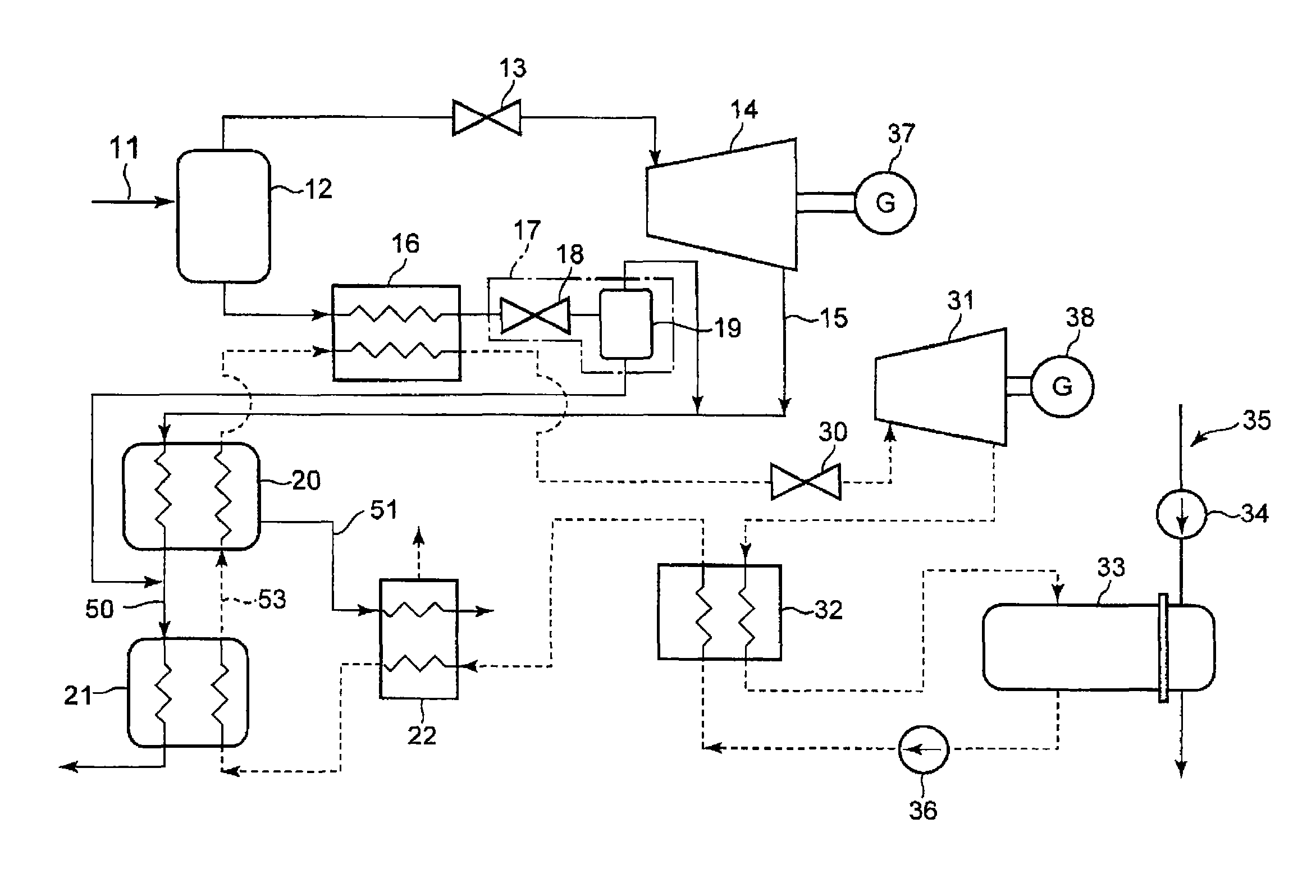
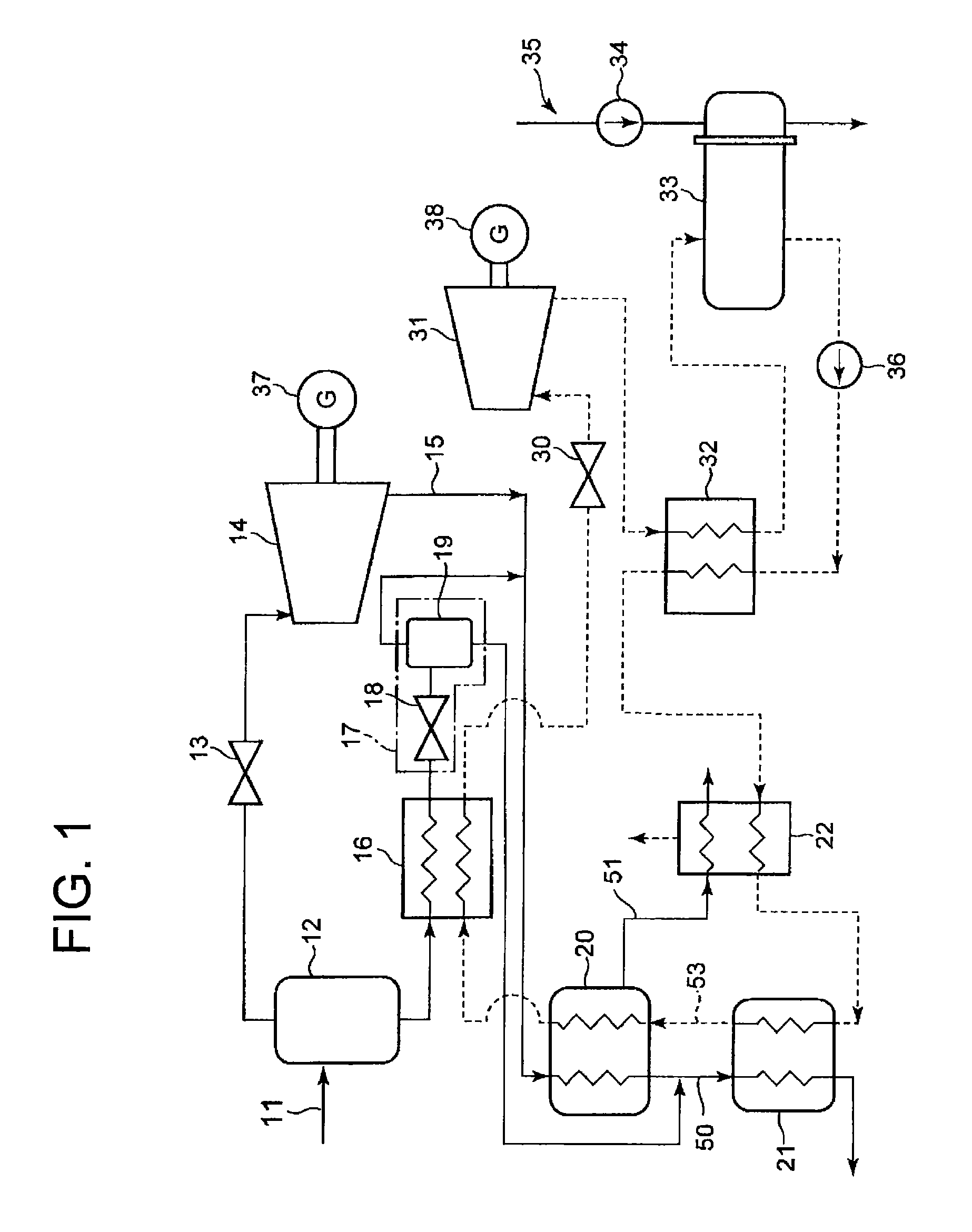
[0034]FIG. 1 is a system diagram showing a configuration of a first embodiment of the binary power generation system according to the present invention.

[0035]

[0036]Initially, a configuration of a heat source water system will be described along a flow of supplied geothermal heat source water.

[0037]Geothermal heat source water piping 11 is connected to a first pressure reducing steam-liquid separator (flasher) 12. Geothermal heat source water supplied to the first pressure reducing steam-liquid separator 12 through the geothermal heat source water piping 11 is reduced in pressure there, and separated into high pressure water steam and high pressure hot water (liquid water). The generated water steam is sent to a steam turbine 14 via a water steam governing valve 13. Low pressure steam having worked in the steam turbine 14 is discharged through steam turbine return piping 15.

[0038]The high pressure hot water generated by the first pressure reducing steam-liquid...

second embodiment

[0050][Second Embodiment]

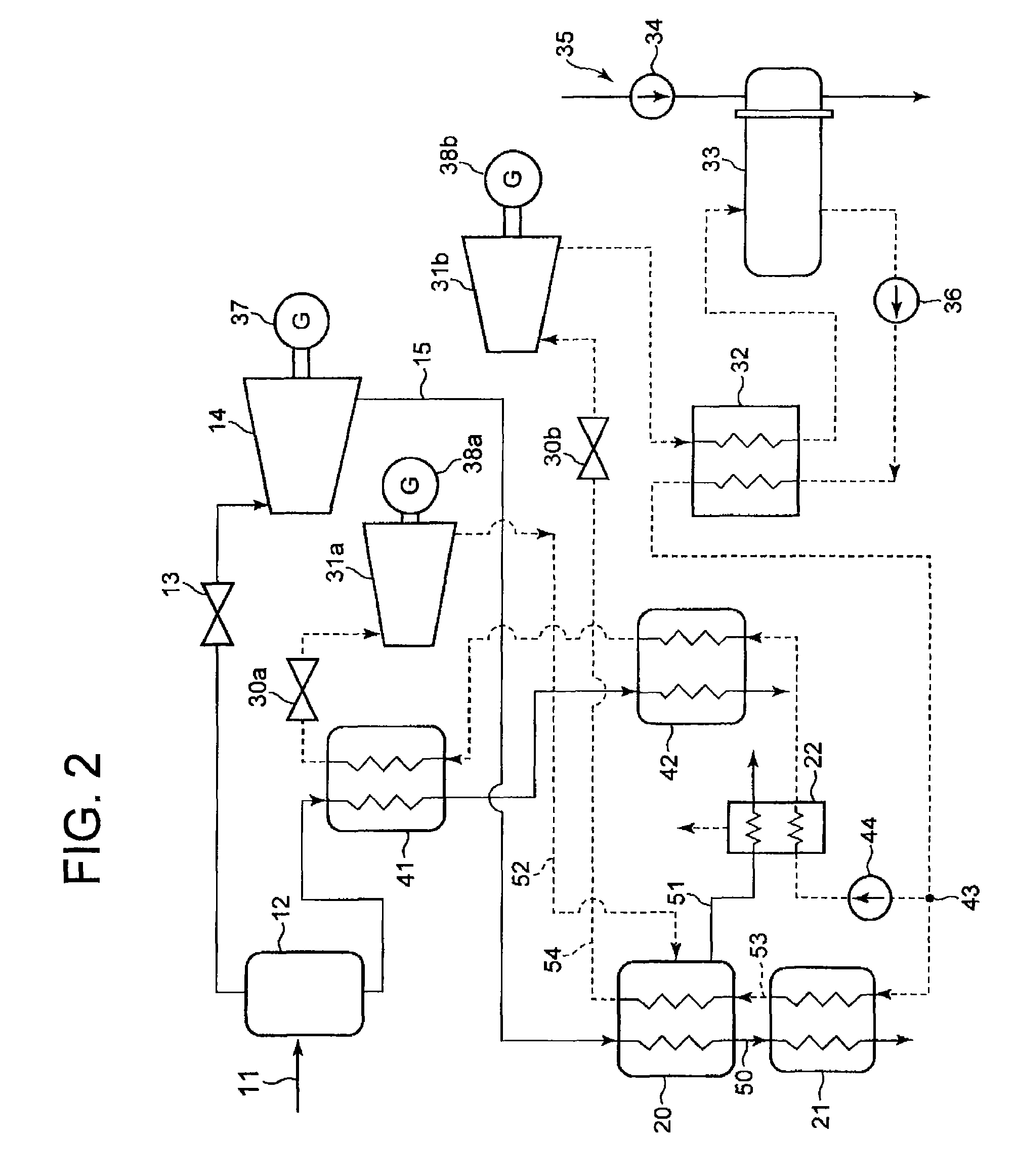
[0051]FIG. 2 is a system diagram showing a configuration of a second embodiment of the binary power generation system according to the present invention. FIG. 3 is a longitudinal sectional view showing a specific configuration of a condenser / evaporator according to the second embodiment.

[0052]

[0053]Geothermal heat source water piping 11 is connected to a first pressure reducing steam-liquid separator 12. Geothermal heat source water supplied to the first pressure reducing steam-liquid separator 12 through the geothermal heat source water piping 11 is reduced in pressure there and separated into high pressure water steam and high pressure hot water (liquid water). The water steam generated here is sent to a steam turbine 14 via a water steam governing valve 13. Low pressure steam having worked in the steam turbine 14 is discharged through steam turbine return piping 15.

[0054]The high pressure hot water (liquid water) generated by the first pressure reducing s...

third embodiment

[0085][Third Embodiment]

[0086]FIG. 4 is a system diagram showing a configuration of a third embodiment of the binary power generation system according to the present invention.

[0087]This embodiment is a modification of the second embodiment. Differences from the second embodiment will be mainly described here.

[0088]In this embodiment, part of the steam is extracted at an intermediate stage. The extracted steam is sent to the condenser / evaporator 20 through the steam turbine return piping 15.

[0089]Water steam discharged from the lowest stage of the steam turbine 14 is sent to a condenser 91 through steam turbine discharge piping 90. The condenser 91 is connected with a cold water system 93 including a cold water pump 92. The cold water system 93 cools the water steam in the condenser 91 into condensate. The pressure inside the condenser 91 is preferably lower than or equal to atmospheric pressure.

[0090]As described above, this embodiment differs from the second embodiment in that the...


PUM


Abstract

A binary power generation system includes: a first pressure reducing steam-liquid separator which reduces the pressure of geothermal heat source water to separate the geothermal heat source water into water steam and hot liquid water; a steam turbine which is driven by geothermal water steam; a medium turbine which is driven by medium vapor obtained by evaporating a medium liquid with the geothermal heat source water as a heat source; a condenser / evaporator which is configured to transfer the heat of the water steam discharged from the steam turbine to the medium liquid so that the water steam is condensed and the medium liquid is evaporated; and a gas cooler which leads a working medium discharged from the medium turbine to thereby cool condensed water obtained by the condenser / evaporator and separate and discharge noncondensable gas contained in the condensed water.

Description

TECHNICAL FIELD[0001]Embodiments of this invention relate to a binary power generation system using geothermal heat.BACKGROUND ART[0002]The greenhouse effect from CO2 has recently been pointed out as one of the causes of the global warming phenomenon. Immediate actions are needed to protect the earth's environment. CO2 sources include human activities of burning fossil fuels, and there is an increasing demand for emission control. As a result, new construction of thermal power plants and the like using large amounts of fossil fuels has been stagnating because of high CO2 emissions.[0003]Demand is increasing for power generation methods using renewable energies that produce no CO2, such as solar light, solar heat, wind power, geothermal heat, and tidal power. Of these, power generation systems using geothermal steam and geothermal water have been commercialized since the 1950s. With high construction costs, geothermal power plants used to decline in the age of decreasing fossil fuel ...

Claims


Application Information

Patent Timeline
Patent Type & Authority Patents(United States)
IPC IPC(8): F03G7/04F01K23/04F28F9/22F01K5/02F24J3/08
CPCF01K23/04F03G7/04F01K5/02F24J3/08F28F9/22Y02E10/10F24J3/085F24T10/20F24T10/00
Inventor YAMASHITA, KATSUYAFURUYA, OSAMUHADIANTO, MOHAMMAND ASHARITAKAYANAGI, MIKIO
Owner KK TOSHIBA
Why Eureka
Try Eureka