Transimpedance amplifier

a technology of transimpedance amplifier and amplifier, which is applied in the direction of mass spectometer, particle separator tube details, instruments, etc., can solve the problems of long charge-up duration of current superimposed, particularly demanding requirements occur quite frequently, and achieve the effect of minimising overshoot and undershoot and minimising the settling time of the amplifier

Active Publication Date: 2016-08-30
THERMO FISHER SCI BREMEN
View PDF10 Cites 9 Cited by
  • Summary
  • Abstract
  • Description
  • Claims
  • Application Information

AI Technical Summary

Benefits of technology

[0031]The voltages applied to the conductive compensation elements may each be different from each other, thus applying different external electric fields to the resistor along its longitudinal length. The voltages applied to the conductive compensation elements may therefore be selected such that a greater external electric field is applied to the resistor at a location where that is required to compensate for the degree of axial and / or radial capacitance and / or dielectric absorption experienced there, and a lesser external electric field applied to the resistor at a location where that is required to compensate for the degree of axial and / or radial capacitance and / or dielectric absorption experienced there. Thus, the unique, non-linear characteristics of each individual feedback resistor may be compensated for on a resistor by resistor basis, resulting in more accurate compensation for each unique resistor.
[0069]Minimising the overshoot and undershoot of the output should minimise the settling time of the amplifier, which, even where the minimisation results in a longer initial signal decay, may be particularly beneficial for applications such as isotope-ratio mass spectrometry.

Problems solved by technology

In such an application, a particularly demanding requirement occurs quite frequently.
A delay of this size might be reasonable for practical experiments, but due to the nature of extremely high impedance resistors and the added capacitor, such ideal parts in practice are not achievable.
Most discrete electronic capacitors have a solid dielectric inside and non-ideal behaviors of the dielectric, such as finite insulation resistance (leakage current) and polarization effects (dielectric absorption), exclude the use of those capacitors.
The value of the shunt impedance for ultrahigh value resistors can be very high, which results in a long charge-up duration of current being superimposed on the real current to be measured.
However, the solutions suggested in GB2424330A and U.S. Pat. No. 7,262,655B2 assume that the feedback resistor is a constant linear device, which, in practice, is not the case for ultra-high value resistors.
As a consequence, when an ultra-high value resistor is being used, the precision and repeatability of amplifier performance may be degraded.
This dielectric absorption introduces a second time constant, which results in a further unwanted delay and / or distortion when measuring very small currents (i.e. femto-ampere).
As can be seen, the dielectric absorption which introduced the second time constant has delayed and distorted the amplifier response, such that the amplifier output may effectively never reach the correct level.
This creep is caused by τ2, and causes a delay and distortion in the amplifier response, such that the amplifier output may effectively never reach the correct level.
Therefore, the solutions described in GB2424330A and U.S. Pat. No. 7,262,655B2 may be ineffectual for the measurement of very small currents using an ultrahigh impedance resistor.

Method used


Image

  • Transimpedance amplifier
  • Transimpedance amplifier
  • Transimpedance amplifier

Examples


Embodiment Construction

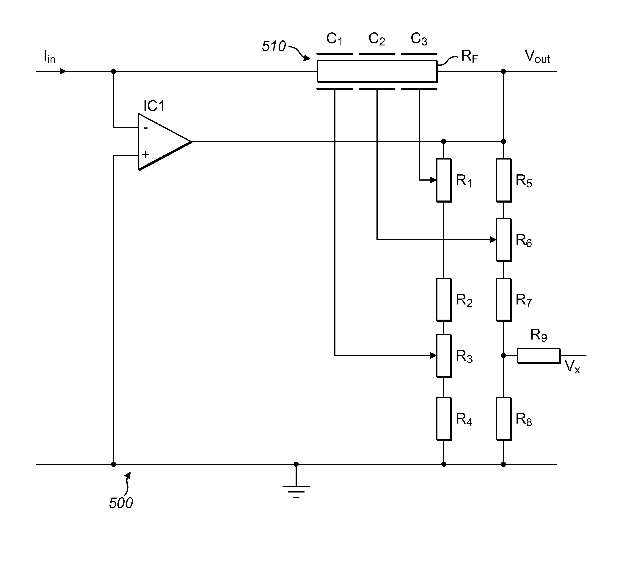
[0093]An ‘ultrahigh value resistor’ may be a resistor with a resistance of approximately 1 TΩ (i.e. 1E12Ω) or more. For example, it may have a resistance of 1-10 TΩ, such as 1 TΩ, 3 TΩ, 8 TΩ or 10 TΩ, or a resistance of 1-100 TΩ, such as 10 TΩ, 20 TΩ, 25 TΩ, 40 TΩ, 60 TΩ, 70 TΩ, 90 TΩ, or 100 TΩ, or a resistance of 10-100 TΩ, such as 50 TΩ or 100 TΩ. Ultrahigh value resistors are of particular use as feedback resistors in transimpedance amplifiers used to measure very low currents, for example in the order of femto-amps (fA), i.e. 1E-15 A.

[0094]FIG. 5 shows a transimpedance amplifier circuit 500 comprising an operational amplifier IC1, a resistor assembly 510 comprising an ultrahigh value feedback resistor RF coupled between the output of the operational amplifier IC1 and the inverting input of the operational amplifier IC1, a first voltage divider comprising resistors R1, R2, R3 and R4 and a second voltage divider comprising R5, R6, R7 and R8. Resistors R1, R3 and R6 are variable r...


PUM


Abstract

A transimpedance amplifier includes a resistor assembly coupled between an output of the transimpedance amplifier and an input of the transimpedance amplifier, and a voltage source for applying a first voltage to a first conductive compensation element of the resistor assembly and a second voltage to a second conductive compensation element of the resistor assembly. The first voltage and the second voltage are each derived from the output voltage, Vout, of the transimpedance amplifier. The first voltage is a first proportion of Vout and the second voltage is a second proportion of Vout. The voltage source includes a voltage controller for adjusting at least one of the first proportion and / or the second proportion.

Description

TECHNICAL FIELD[0001]The present disclosure relates to a transimpedance amplifier, a method for configuring a transimpedance amplifier and a method for using a transimpedance amplifier.BACKGROUND[0002]There is a number of applications where it is necessary to measure currents across a high dynamic range with a good signal to noise ratio. For example, in isotope-ratio mass spectrometry, there is a need for an amplifier with the ability to respond accurately to signals with a high dynamic range and measure isotopic abundance with high precision. In such an application, a particularly demanding requirement occurs quite frequently. The amplifier must first measure a relatively large ion-current. This input signal fades out quickly and a few seconds later a relatively very weak second ion-current occurs (caused by a small isotopic abundance). The amplifier must be able to handle both the fast fade-out of the first signal and make a precise measurement of the relatively weak current signa...

Claims


Application Information

Patent Timeline
Patent Type & Authority Patents(United States)
IPC IPC(8): H03F3/45H01J49/02
CPCH03F3/45475H01J49/022H03F1/083H03F3/45071H03F2203/45288H03F2200/135H03F2200/144H03F2203/45522H03F2200/129H03F2203/45526H03F2203/45512H03F2203/45222H03F2203/45528G01R29/24H01C1/06H01J49/26H03F3/70
Inventor LERCHE, HEINZ
Owner THERMO FISHER SCI BREMEN
Why Eureka
Try Eureka