Silver barrier materials for low-emissivity applications

a technology of low emissivity and silicon barrier, applied in the direction of instruments, lighting and heating apparatus, optical elements, etc., can solve the problems of reduced visible light transmission of reflective layers and increased overall manufacturing costs, and achieve the effects of reducing optical absorption, reducing ti-ag reactivity, and reducing overall manufacturing costs

Inactive Publication Date: 2016-09-20
GUARDIAN GLASS LLC
View PDF7 Cites 0 Cited by
  • Summary
  • Abstract
  • Description
  • Claims
  • Application Information

AI Technical Summary

Benefits of technology

[0005]In some embodiments, the present invention discloses a barrier structure, and method for forming the same, for an infrared reflective layer to be used in low emissivity coatings. The barrier structure can include an alloy of a first element having high oxygen affinity with a second element having low oxygen affinity. The high oxygen affinity property of the first element can prevent oxidation of the infrared reflective layer by attracting oxygen, for example, from the deposition of subsequent layers or from the subsequent high temperature processes. The low oxygen affinity property of the second element can improve adhesion with the infrared reflective layer. The ratio of the first and second elements can be optimized, for example, the amount of the second element can be minimal, selected to achieve adequate adhesion. The amount of the first element can be maximized, selected to achieve the oxygen diffusion barrier.
[0007]The barrier layer can reduce optical absorption in the visible range, providing higher transmission, for example, through the elimination of Cr from the industry-standard NiCr barrier material. Further, more color-neutral product can be achieved, for example, by minimizing reactivity of Ti—Ag at the interface, such as through reducing the concentration of Ti from 100% to a different binary alloy, or through completely eliminating Ti. In addition, adhesion can be improved, e.g., compared to Ti, due to the existence of an element with lower oxygen affinity to maintain good adhesion to Ag.

Problems solved by technology

However, as the thickness of the silver layer increases, the visible light transmission of the reflective layer is reduced, as is manufacturing throughput, while overall manufacturing costs are increased.

Method used


Image

  • Silver barrier materials for low-emissivity applications
  • Silver barrier materials for low-emissivity applications
  • Silver barrier materials for low-emissivity applications

Examples


Embodiment Construction

[0016]A detailed description of one or more embodiments is provided below along with accompanying figures. The detailed description is provided in connection with such embodiments, but is not limited to any particular example. The scope is limited only by the claims and numerous alternatives, modifications, and equivalents are encompassed. Numerous specific details are set forth in the following description in order to provide a thorough understanding. These details are provided for the purpose of example and the described techniques may be practiced according to the claims without some or all of these specific details. For the purpose of clarity, technical material that is known in the technical fields related to the embodiments has not been described in detail to avoid unnecessarily obscuring the description.

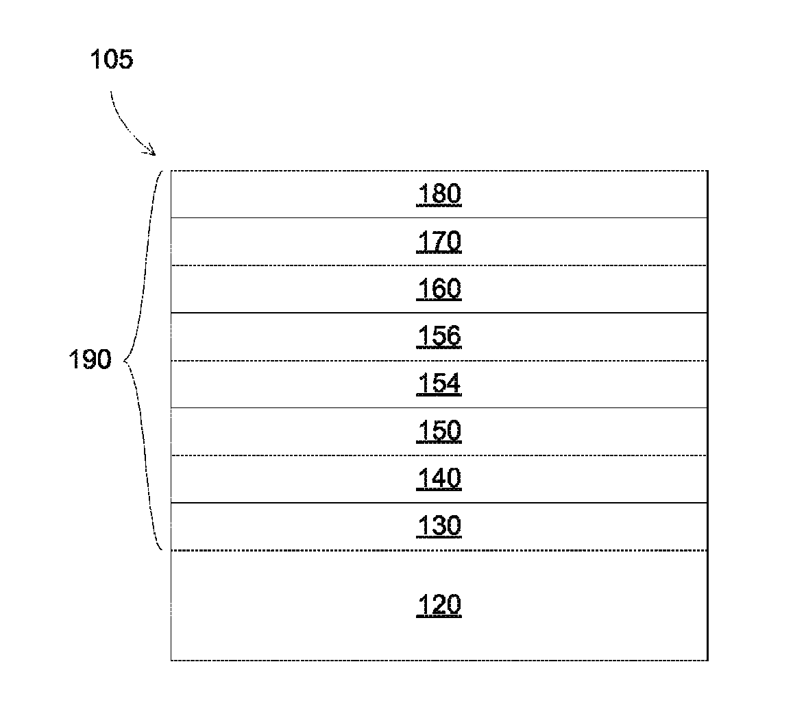
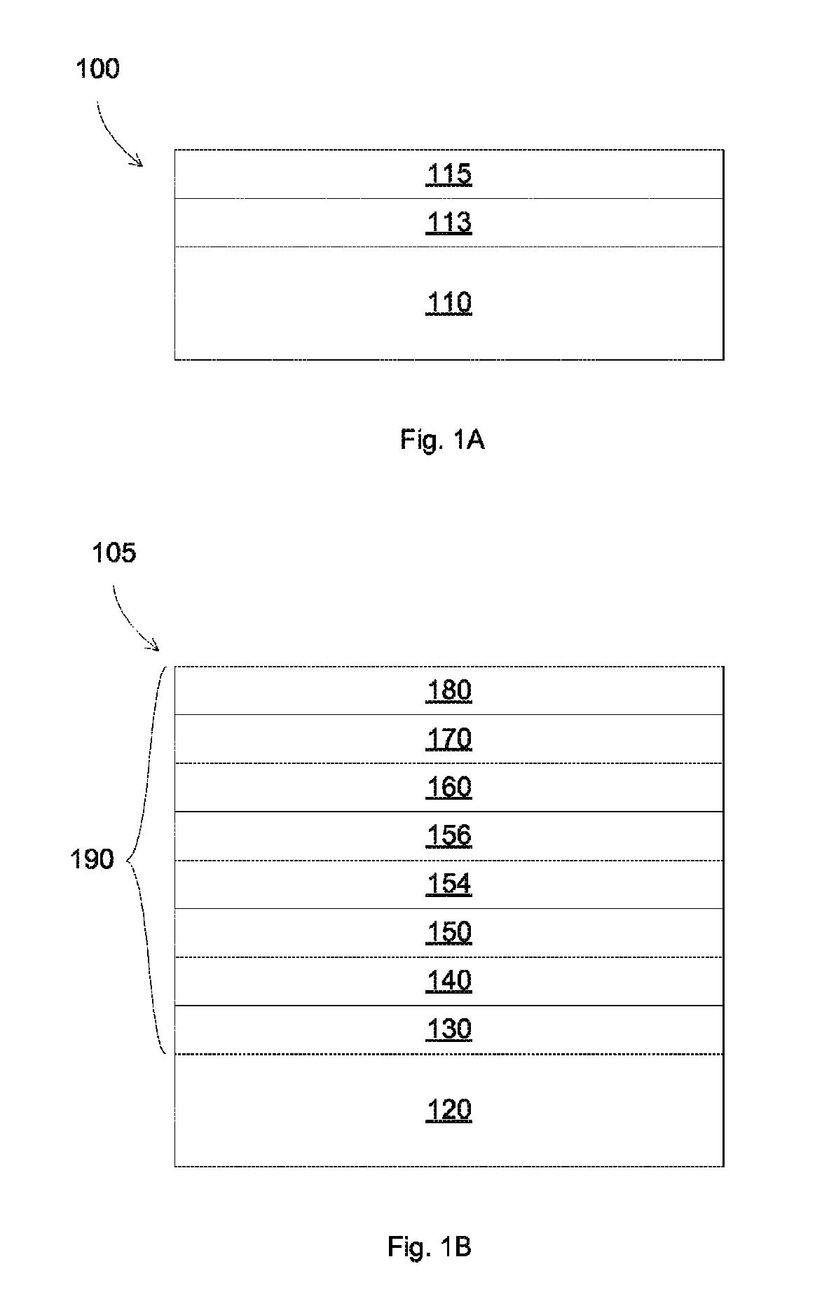
[0017]In some embodiments, methods and apparatuses for making coated panels are disclosed. The coated panels can include coated layers formed thereon, such as a low resistivit...


PUM

PropertyMeasurementUnit
wt %aaaaaaaaaa
wt %aaaaaaaaaa
wt %aaaaaaaaaa

Abstract

A method for making low emissivity panels, including control the composition of a barrier layer formed on a thin conductive silver layer. The barrier structure can include an alloy of a first element having high oxygen affinity with a second element having low oxygen affinity. The first element can include Ta, Nb, Zr, Hf, Mn, Y, Si, and Ti, and the second element can include Ru, Ni, Co, Mo, and W, which can have low oxygen affinity property. The alloy barrier layer can reduce optical absorption in the visible range, can provide color-neutral product, and can improve adhesion to the silver layer.

Description

FIELD OF THE INVENTION[0001]The present invention relates generally to films providing high transmittance and low emissivity, and more particularly to such films deposited on transparent substrates.BACKGROUND OF THE INVENTION[0002]Sunlight control glasses are commonly used in applications such as building glass windows and vehicle windows, typically offering high visible transmission and low emissivity. High visible transmission can allow more sunlight to pass through the glass windows, thus being desirable in many window applications. Low emissivity can block infrared (IR) radiation to reduce undesirable interior heating.[0003]In low emissivity glasses, IR radiation is mostly reflected with minimum absorption and emission, thus reducing the heat transferring to and from the low emissivity surface. Low emissivity, or low-e, panels are often formed by depositing a reflective layer (e.g., silver) onto a substrate, such as glass. The overall quality of the reflective layer, such as wit...

Claims


Application Information

Patent Timeline
Patent Type & Authority Patents(United States)
IPC IPC(8): G02B5/28F21V9/00G02B5/20C03C17/36
CPCG02B5/208C03C17/366G02B5/282C03C17/36C03C17/3644C03C17/3649C03C17/3652C03C17/40C22C5/06C22C14/00C22C27/02
Inventor HASSAN, MOHD FADZLI ANWARBOYCE, BRENTDING, GUOWENLE, MINH HUUSUN, ZHI-WEN WENWANG, YUXU, YONGLI
Owner GUARDIAN GLASS LLC
Why Eureka
Try Eureka