
Power control system and method of controlling the same

a power control system and power control technology, applied in the direction of electric generator control, mechanical equipment, machines/engines, etc., can solve the problems of large number of loads, affecting overall power generation, and easy damage to the joints of the tail, etc., to achieve accurate and higher resolution of power control

Inactive Publication Date: 2016-10-18
DELTA ELECTRONICS INC
View PDF4 Cites 0 Cited by
  • Summary
  • Abstract
  • Description
  • Claims
  • Application Information

AI Technical Summary

Benefits of technology

The present invention provides a power control system for a generator that can output power in a more accurate and precise manner. The system uses multiple power curves that are shifted and a small amount of load-dumping resistors to protect the generator, ensuring higher resolution power controls and maximum power output at wide-range wind speed operations. The method includes using a sensing unit to receive current and voltage generated from the generator, a control unit to produce current and voltage control signals, and a power conversion unit and load-dumping unit to control the output power of the generator.

Problems solved by technology

Also, the variable pitch control is usually realized for the middle-scale and large-scale wind power generation system because of high costs, high damage rate, and complicated control of the blade mechanism.
However, the joints of the tail are easily damaged when the tail swings for months and years.
Because a third-order relationship is between the output power of the generator and the wind speed, a large number of loads are needed once the generator is operated at the over-rated wind speed.
However, unstable wind conditions probably make the generator fail in loading due to instantaneous gusty wind, thus affecting overall power generation.

Method used


Image

  • Power control system and method of controlling the same
  • Power control system and method of controlling the same
  • Power control system and method of controlling the same

Examples


Embodiment Construction

[0020]Reference will now be made to the drawing figures to describe the present invention in detail.

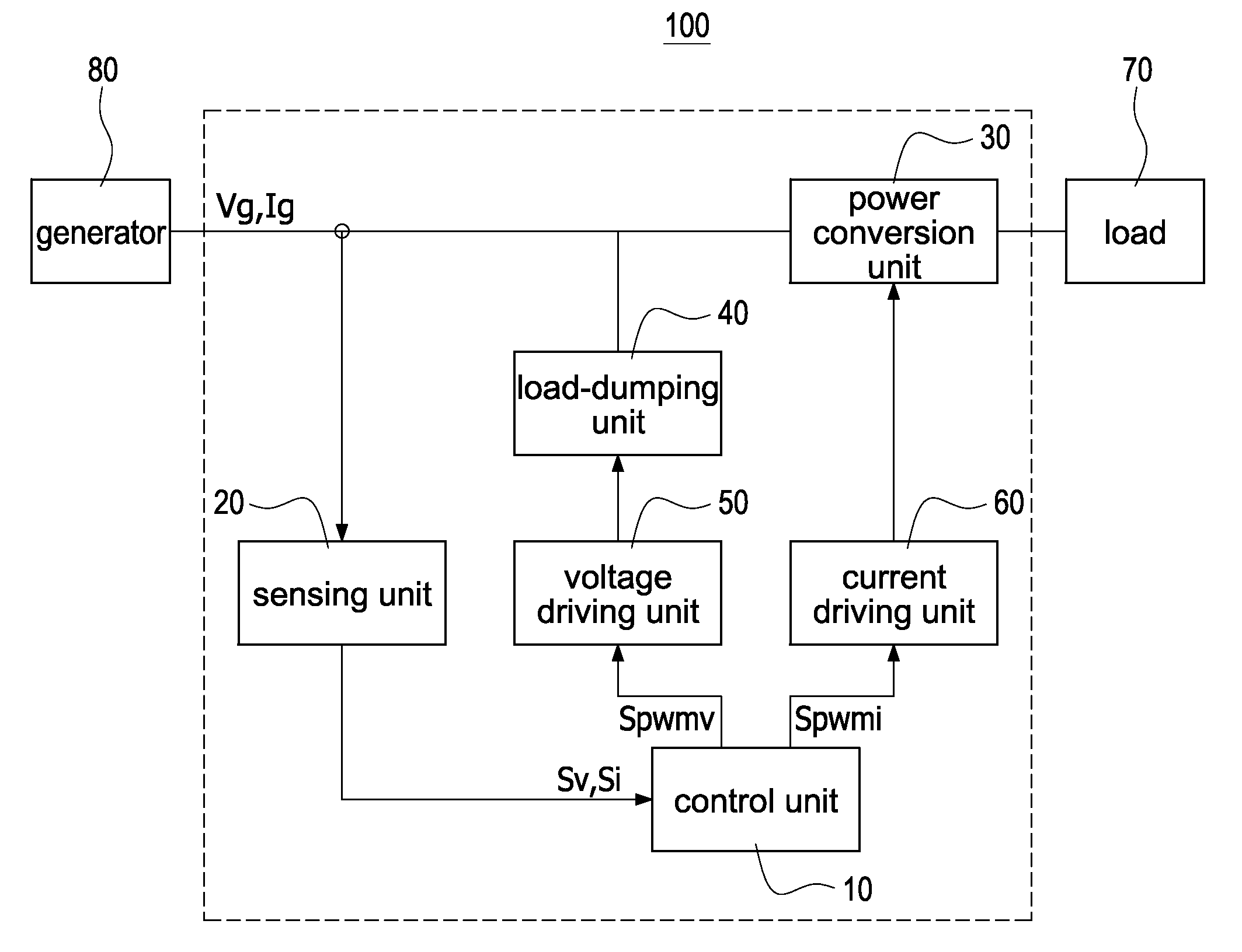
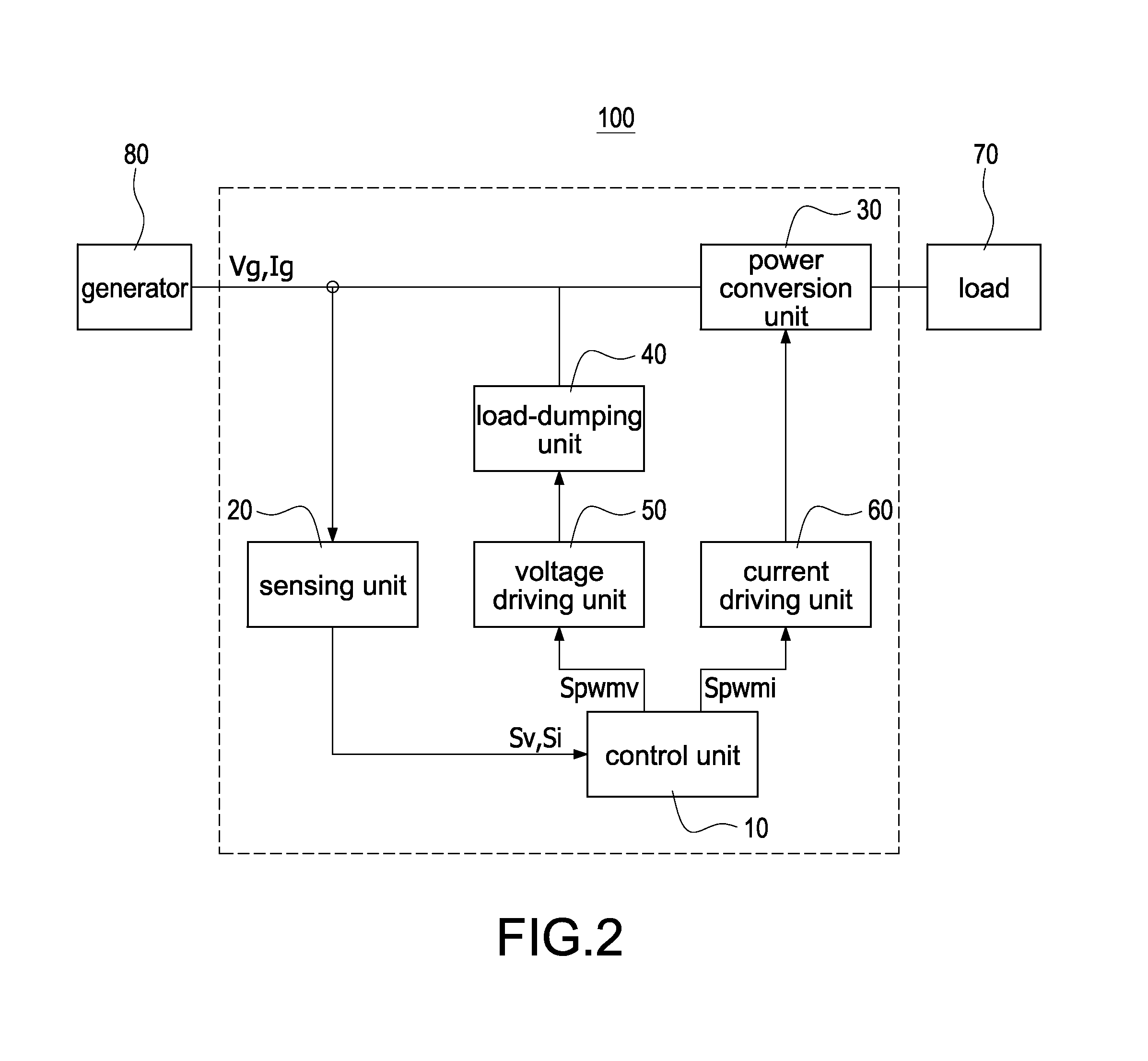
[0021]FIG. 2 is a circuit block diagram of a power control system of a generator according to the present invention. The power control system 100 provides the power control to a generator 80 driven by an external force, such as wind power, hydraulic power, vapor power, or even human power. However, the embodiments are only exemplified but are not intended to limit the scope of the disclosure. The power control system 100 includes a power conversion unit 30, a sensing unit 20, a load-dumping unit 40, and a control unit 10. The sensing unit 20 is connected to a side of the generator 80 or between the load-dumping unit 40 and the power conversion unit 30. The load-dumping unit 40 is electrically connected to the generator 80 and the power conversion unit 30. The control unit 10 is electrically connected to the sensing unit 20 and the power conversion unit 30.

[0022]The power conversion un...


PUM


Abstract

A power control system provides an output power control for a generator. The power control system includes a power conversion unit, a sensing unit, a load-dumping unit, and a control unit. The power conversion unit receives and converts a current and a voltage, generated from the generator, to supply a load. The sensing unit receives the current and the voltage to produce a current signal and a voltage signal. The load-dumping unit is connected to the generator and the power conversion unit. The control units receives the current signal and the voltage signal, produces a current control signal to control the power conversion unit, and generates a voltage control signal to control the load-dumping so as to control the output power of the generator.

Description

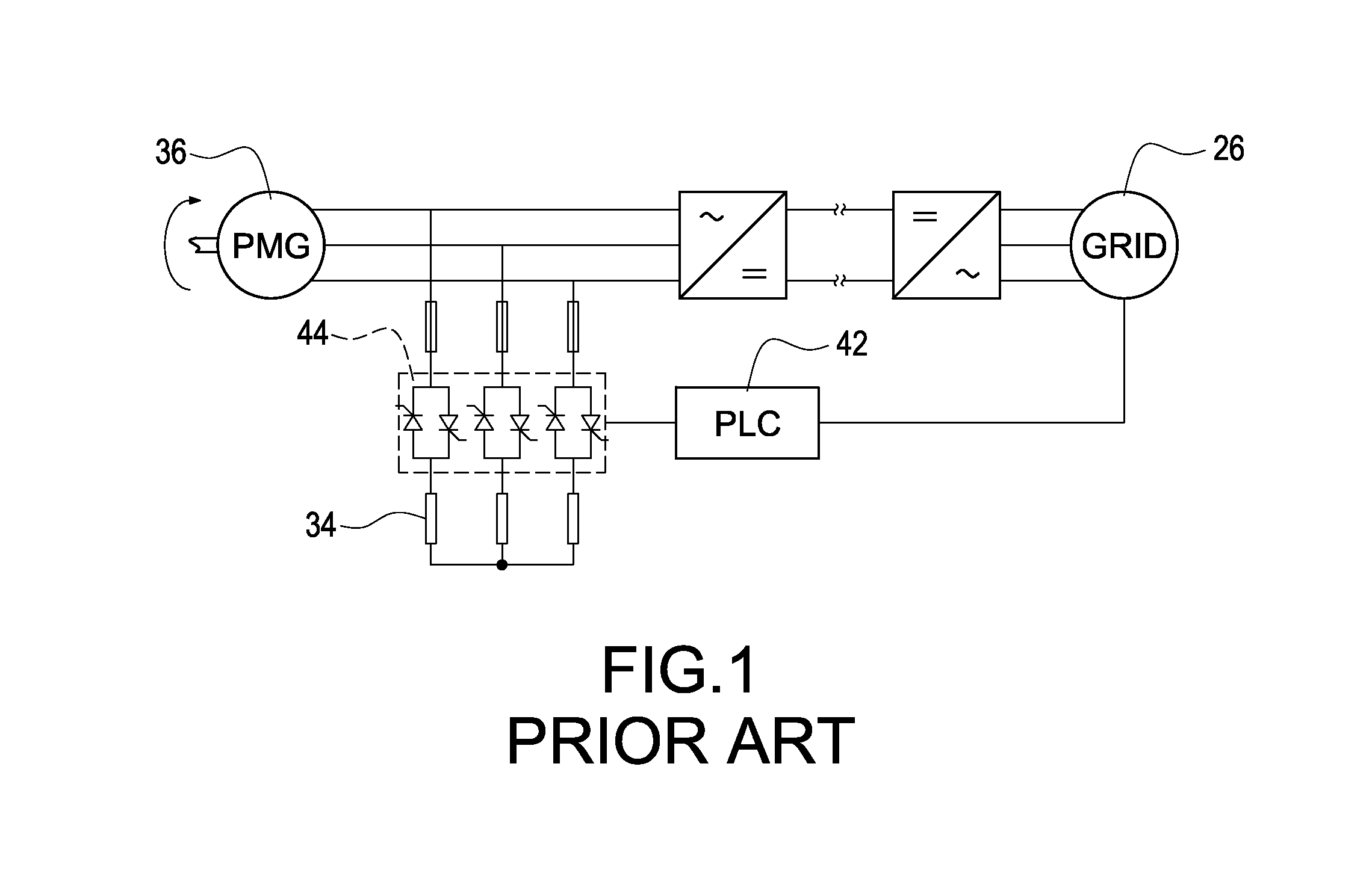
BACKGROUND[0001]1. Technical Field[0002]The present invention relates generally to a power control system and method; and more particularly to a power control system for providing the output power control of a generator by shifting power curves of the generator.[0003]2. Description of Related Art[0004]The common solutions for the problem that the wind power generation system is operated at the over-rated wind speed condition can be divided into the variable pitch control, yaw control, load-dumping control, torque increasing control, and direct short-circuit control. The variable pitch control is used to indirectly capture wind energy by controlling the windward angle of the blade. Also, the variable pitch control is usually realized for the middle-scale and large-scale wind power generation system because of high costs, high damage rate, and complicated control of the blade mechanism. The yaw control is used for reduction of capturing wind energy by tail deviation. However, the join...

Claims


Application Information

Patent Timeline
Patent Type & Authority Patents(United States)
IPC IPC(8): F03D9/00H02P9/04F03D7/02H02J1/00H02P9/10
CPCF03D9/002F03D7/0272H02J1/00H02P9/107Y02E10/723Y02E10/725H02P9/00H02P9/48F03D9/25Y02E10/72
Inventor HSIAO, CHIH-HUNGWEI, JO-FANG
Owner DELTA ELECTRONICS INC
Learn More