In-situ battery device for soft X-ray microscopic imaging

A technology for microscopic imaging and battery devices, which can be used in measuring devices, secondary battery testing, and secondary battery repair/maintenance. It can solve problems such as irreversible changes, technical difficulties, and high prices, and achieve accurate and high-resolution soft X-rays. Imaging, wide applicability effects

Inactive Publication Date: 2022-04-19
UNIV OF SCI & TECH OF CHINA
View PDF0 Cites 0 Cited by
  • Summary
  • Abstract
  • Description
  • Claims
  • Application Information

AI Technical Summary

Problems solved by technology

[0003] Although ex situ imaging techniques can provide a lot of valuable information about battery materials, the test results are not necessarily completely accurate because they cannot be tested in a real reaction environment
For example, during the charge-discharge cycle, the non-equilibrium process and the transient process of the reaction, i.e., the mesophase and possibly the metastable phase, are hardly observed
And since the ex situ characterization of a single particle requires disassembly of the battery, it is technically very difficult to track the same particle over multiple repeated charge-discharge cycles.
In addition, due to the high sensitivity of some electrode materials to oxygen and moisture, which may be contaminated, irreversibly changed when handling, transferring samples, these results may mislead the understanding of the reaction and degradation mechanism
[0004] Soft X-ray imaging technology is a non-destructive testing technology with high resolution and strong penetrability. Compared with electron microscopy, soft X-ray has higher penetration ability to electrode particles and electrolyte and less radiation damage. However, when hard X-rays are used to observe single particles with high light element content or small thickness (about 1 micron), the imaging contrast is poor, so the effect of tracking the spatial evolution of the same micron-sized particle and the solid-liquid interface in the liquid not good
[0005] At present, the in situ imaging technology based on soft X-rays is still in its infancy. Due to the limitation of imaging conditions (working distance, ultra-high vacuum, sample stage size, soft X-ray penetration ability, etc.), the in situ imaging technology of micron-sized single particles can be realized. Bit imaging is very difficult
At present, only Lim et al. of Stanford University have designed an in-situ battery device for STXM (scanning transmission X-ray microscope), but the overall device structure is complex; and the processing requirements for microfluidic chips and battery devices are relatively high, and the price is relatively high. expensive

Method used


Image

  • In-situ battery device for soft X-ray microscopic imaging
  • In-situ battery device for soft X-ray microscopic imaging
  • In-situ battery device for soft X-ray microscopic imaging

Examples


Embodiment 1

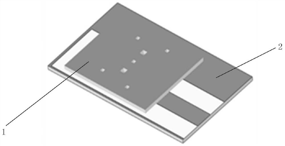
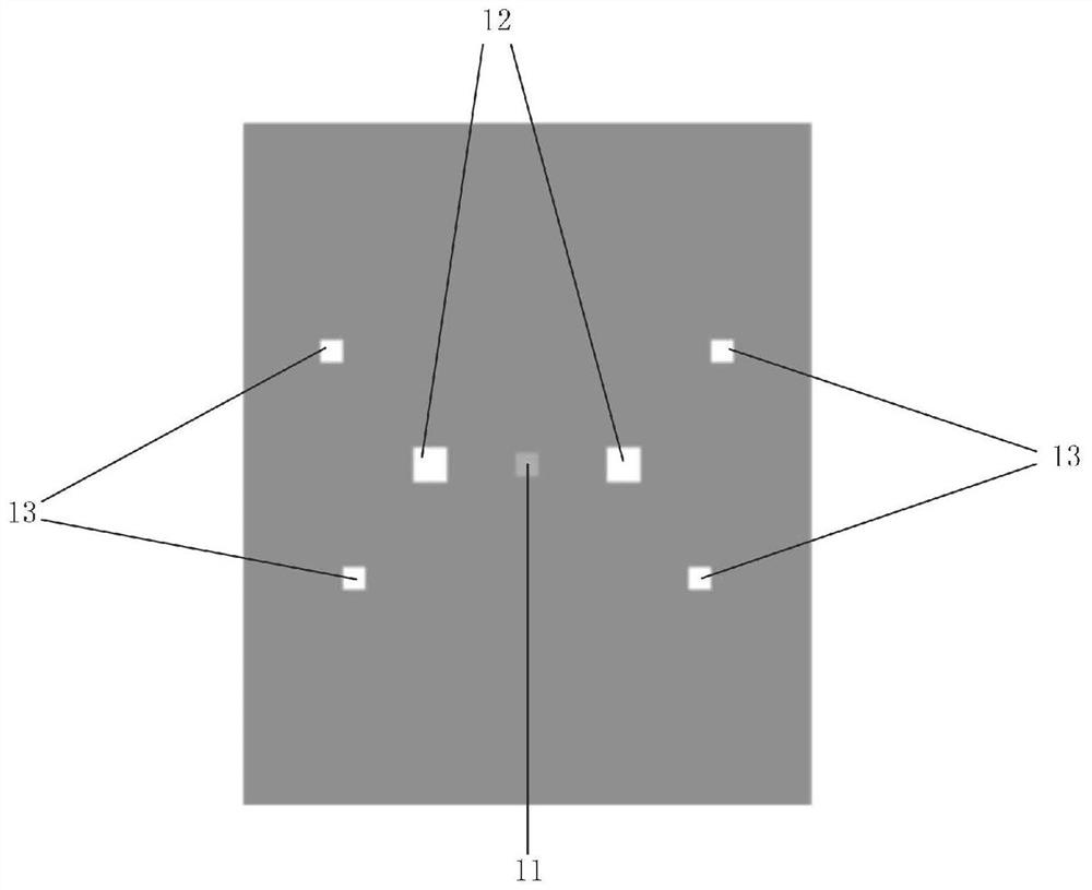
[0017] An in-situ battery device for soft X-ray microscopic imaging provided by an embodiment of the present invention includes:

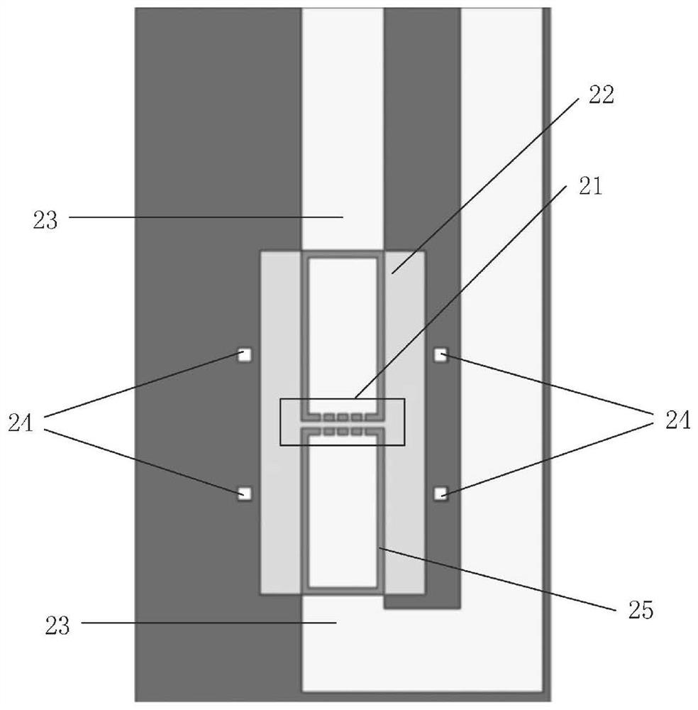
[0018] An upper silicon wafer (1) and a lower silicon wafer (2); respectively open an upper observation window (11) and a lower observation window (21) on the upper silicon wafer (1) and the lower silicon wafer (2). A liquid injection port (12) is opened on both sides of the observation window (11); a liquid pool (22) is opened on the lower silicon wafer (2), so that the width of the liquid pool (22) is greater than two liquid injection ports (12) Distance between them; 2 electrodes (23) are made on the lower silicon wafer (2), so that one end of the 2 electrodes (23) is relatively placed in the liquid pool (22) and separated by a certain gap, and the gap is located at the upper observation window (11 ) and the area covered by the lower observation window (21), the electrode (23) area in the liquid pool (22) is only left with a single layer of elec...

Embodiment 2

[0026] Due to the small size of the injection port of the upper silicon chip of the in-situ battery in the embodiment of the present invention, the electrolyte needs to be added in a glove box, and the traditional method of first dropping the electrolyte and then aligning the two chips for sealing is no longer necessary Be applicable. In order to facilitate the operation and prevent the silicon wafer from moving, it is necessary to align the upper and lower silicon wafers under the microscope, and then use ultraviolet glue to fix the edges of the connection between the two chips, then remove the silicon wafer from the microscope, and use epoxy resin to completely seal the two silicon wafers. Gap between slices. In the glove box, drop the electrolyte solution at the liquid injection port, completely cover the liquid suction port with a flat syringe with a hose, and slowly pull up the core rod, you can see that the liquid drop at the liquid injection port gradually becomes small...


PUM


Abstract

The invention relates to an in-situ battery device for soft X-ray microscopic imaging. The in-situ battery device comprises an upper silicon wafer and a lower silicon wafer, the upper silicon wafer and the lower silicon wafer are respectively provided with an upper observation window and a lower observation window, and two sides of the upper observation window are respectively provided with a liquid extraction and injection port; a liquid pool is formed in the lower silicon wafer, so that the width of the liquid pool is larger than the distance between the two liquid pumping and injecting openings; two electrodes are manufactured on the lower silicon wafer, one ends of the two electrodes are oppositely arranged in the liquid pool and keep a certain gap, the gap is located in the area covered by the view of the upper observation window and the view of the lower observation window, only single-layer electrode particles are reserved after the electrode area in the liquid pool is impressed by the PDMS block, and the other ends of the two electrodes extend out of the liquid pool; and at least one upper through hole and at least one lower through hole are respectively formed in corresponding positions around the upper and lower observation windows. According to the in-situ battery device and the imaging method provided by the invention, the applicability is relatively wide, the single-layer electrode particles are adopted, a relatively large distance exists between the electrode particles under soft X-rays, and accurate high-resolution soft X-ray imaging of the single-layer electrode particles can be realized.

Description

technical field [0001] The invention relates to the field of synchrotron radiation CT imaging and in-situ devices, in particular to an in-situ battery device for soft X-ray microscopic imaging. Background technique [0002] In the field of energy materials, with the explosive growth of portable devices and electric vehicles, the need to develop next-generation batteries with excellent performance and high safety is becoming more and more urgent. The development of such advanced batteries requires the optimization of existing materials, as well as the discovery and utilization of new battery materials with better electrochemical performance. At present, most of the commonly used battery materials are micron-sized particles. During characterization, the mixed information of multi-particle signal superposition will be obtained at the same time, and it is impossible to accurately characterize single particles. In order to elucidate the reaction and degradation mechanism of batt...

Claims


Application Information

Patent Timeline
Patent Type & Authority Applications(China)
IPC IPC(8): G01N23/046G01N23/2251H01M10/42
CPCG01N23/046G01N23/2251H01M10/4285Y02P70/50
Inventor 田扬超丁旭熊瑛关勇吴朝刘刚
Owner UNIV OF SCI & TECH OF CHINA
Why Eureka
Try Eureka