High-efficiency molten carbonate fuel cell system and method

a fuel cell and molten carbonate technology, applied in the direction of fuel cells, fuel cell grouping, fuel cells, etc., can solve the problems of material and cost disadvantages, and achieve the effect of increasing the overall fuel utilization and electrical efficiency of the system

Active Publication Date: 2016-10-25
FUELCELL ENERGY INC
View PDF10 Cites 17 Cited by
  • Summary
  • Abstract
  • Description
  • Claims
  • Application Information

AI Technical Summary

Benefits of technology

[0015]It is an objective of the present invention to provide a cost-effective, modular fuel cell system, in which higher overall fuel utilization greater than 80% and higher electrical and conversion system efficiency greater than 55% are achieved while maintaining thermal balance within the fuel cells.
[0017]It is a further objective of the present invention to provide a fuel cell system in which the fuel utilization in the topping and bottoming fuel cell modules is controlled so as to increase the overall fuel utilization and electrical efficiency of the system.
[0020]In some embodiments of the invention, the bottoming anode portion further receives supplemental fuel, and the high efficiency fuel cell system further comprises a controller for controlling the amount of supplemental fuel conveyed to the bottoming anode portion. The controller controls the amount of current generated in the bottoming fuel cell assembly based on the amount of supplemental fuel conveyed to the bottoming anode portion. The controller also controls the amount of current generated in the topping and bottoming fuel cell assemblies so that as operating time of the high efficiency fuel cell system increases, the amount of current generated by the topping fuel cell assemblies decreases and the amount of current generated by the bottoming fuel cell assemblies increases. Moreover, the controller controls the amount of current generated in the bottoming fuel cell assembly based on electricity needs so that the amount of current generated in the bottoming fuel cell assembly is increased when the electricity need increases.
[0024]Each of the fuel cell stacks of the topping and bottoming fuel cell modules include opposing anode inlet and outlet faces and opposing cathode inlet and outlet faces, and have design features to improve thermal uniformity within the fuel cells. These design features include one or more of: (a) each fuel cell stack of the bottoming fuel cell module is configured so as to create a temperature gradient in an area adjacent the cathode inlet face of the fuel cell stack so that the temperature of cathode inlet gas is higher near the anode inlet face of the fuel cell stack than near the anode outlet face of the fuel cell stack; (b) each fuel cell stack of the bottoming fuel cell module is configured so as to create a temperature gradient in an area adjacent the anode inlet face of the fuel cell stack so that the temperature of anode inlet gas is higher near the cathode inlet face of the fuel cell stack than near the cathode outlet face of the stack; and (c) each fuel cell stack of the topping fuel cell module is configured so as to create a temperature gradient in an area adjacent the cathode inlet face of the fuel cell stack so that the temperature of cathode inlet gas is higher near the anode outlet face of the fuel cell stack than near the anode inlet face of the fuel cell stack. In such cases, the temperature gradient is between 10 and 20 degrees F.; and / or each fuel cell stack includes one or more appropriately placed baffles for controlling gas flow so as to form the temperature gradient.

Problems solved by technology

Additionally, this system requires a high temperature air-to-air heat exchanger resulting in material and cost disadvantages.

Method used


Image

  • High-efficiency molten carbonate fuel cell system and method
  • High-efficiency molten carbonate fuel cell system and method
  • High-efficiency molten carbonate fuel cell system and method

Examples


Embodiment Construction

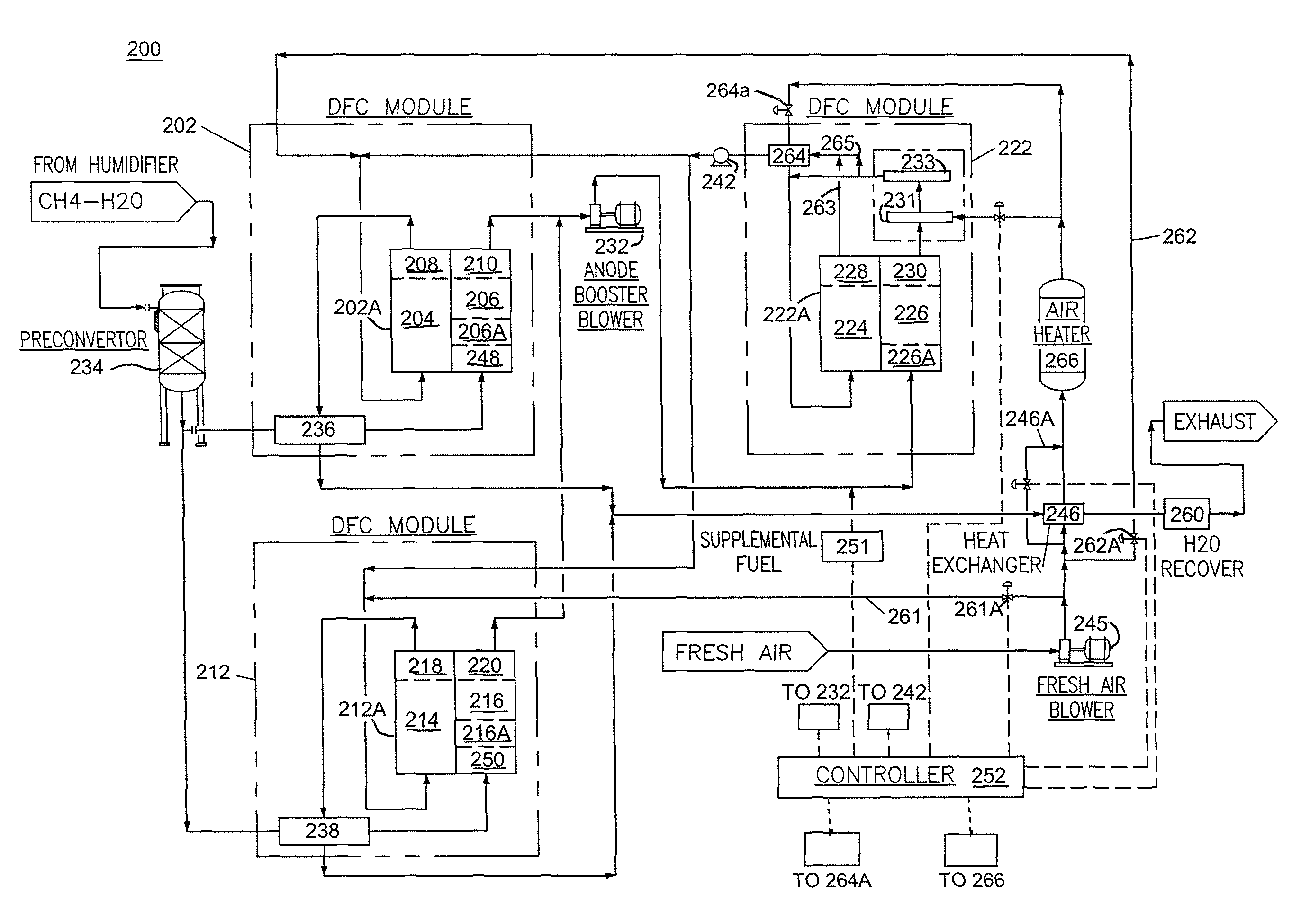
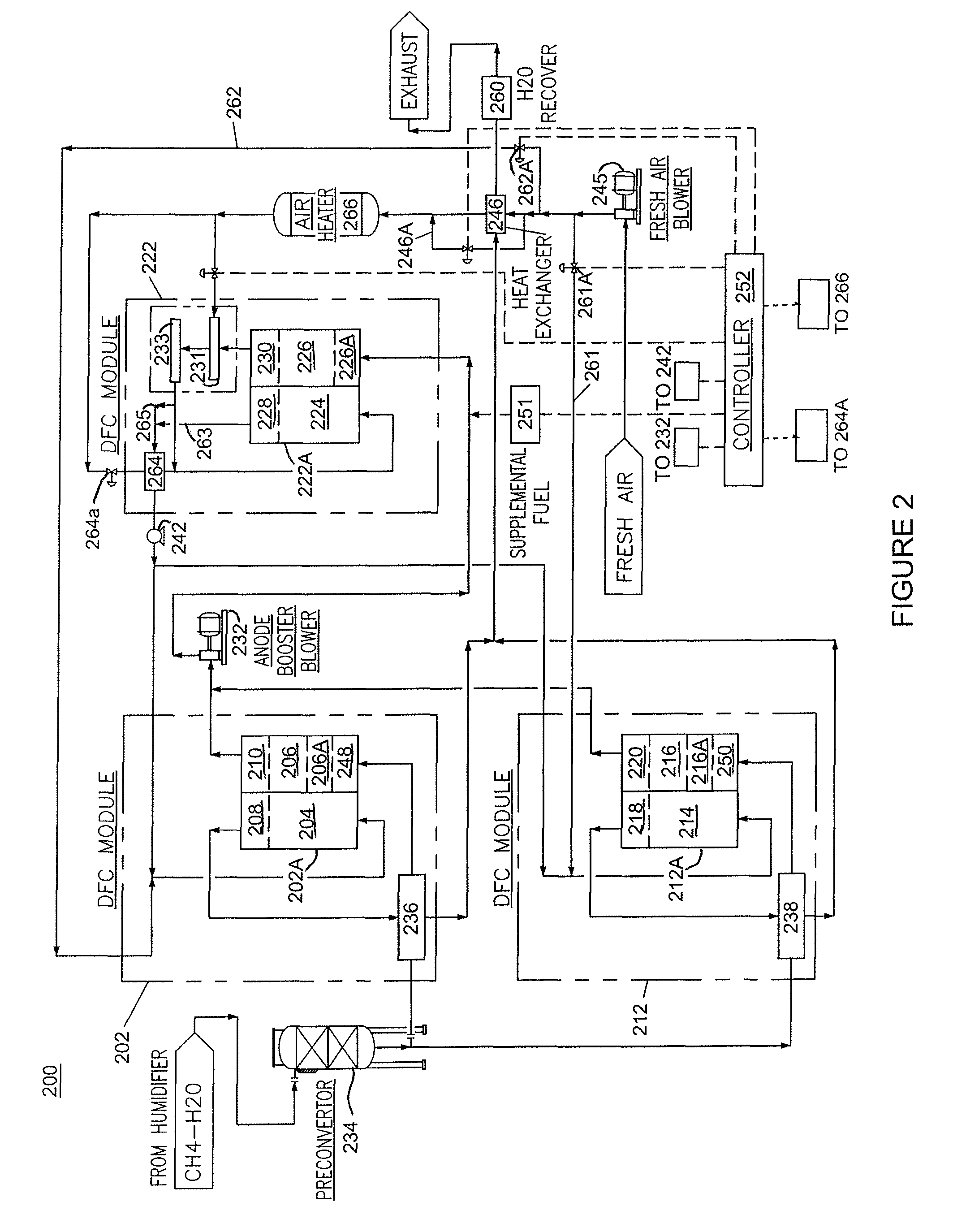
[0033]As shown and described below, the present invention provides a cost-effective, modular fuel cell system, in which higher overall fuel utilization and higher electrical power output and conversion system efficiency are achieved while maintaining thermal balance within the fuel cells. In accordance with the present invention, the fuel cell system includes a plurality of fuel cell stacks or a plurality of fuel cell stack modules including topping stack(s) or topping stack module(s) and bottoming stack(s) or bottoming stack module(s), and wherein the topping stack(s) / module(s) receive fresh fuel and partially spent fuel from the exhaust of the topping fuel cell stack(s) / module(s) is supplied to the bottoming fuel cell stack(s) / module(s). In the configuration of the system of the present invention, fuel utilization in the topping and bottoming fuel cell stacks / modules are controlled within desired limits while still increasing the overall fuel utilization and electrical efficiency ...


PUM

PropertyMeasurementUnit
current densityaaaaaaaaaa
currentaaaaaaaaaa
pressureaaaaaaaaaa

Abstract

A high efficiency fuel cell system comprising a topping fuel cell assembly comprising a topping cathode portion and a topping anode portion; and a bottoming fuel cell assembly comprising a bottoming cathode portion and a bottoming anode portion, wherein the bottoming anode portion receives anode exhaust output from the topping anode portion and the topping cathode portion receives cathode exhaust from the bottoming cathode portion, and wherein the topping fuel cell assembly has a greater number of fuel cells than the bottoming fuel cell assembly so that the topping fuel cell assembly utilizes more fuel than the bottoming fuel cell assembly.

Description

BACKGROUND OF THE INVENTION[0001]This invention relates to fuel cell power production systems and, in particular, to a multi-stack high-efficiency fuel cell system and method of operating same.[0002]A fuel cell is a device which directly converts chemical energy stored in hydrocarbon fuel into electrical energy by means of an electrical reaction. Generally, a fuel cell comprises an anode and a cathode separated by an electrolyte matrix, which conducts electrically charged ions. In order to produce a useful power level, a number of individual fuel cells are stacked in series with an electrically conductive separator plate between each cell.[0003]In building fuel cell systems, individual fuel cells are stacked together to form a fuel cell stack. The number of fuel cells determines the power rating of the fuel cell stack. To provide systems with higher power ratings, a number of fuel cell stacks are utilized and the outputs of the fuel cell stacks are combined to provide the desired po...

Claims


Application Information

Patent Timeline
Patent Type & Authority Patents(United States)
IPC IPC(8): H01M8/06H01M8/04H01M8/24H01M8/14
CPCH01M8/141H01M8/0491H01M8/04104H01M8/04156H01M8/249H01M2008/147H01M8/2465H01M8/04089H01M8/04731H01M8/04753Y02E60/50
Inventor LAMBRECH, MATTHEWFAROOQUE, MOHAMMADJUHAS, CARLAJAHNKE, FRED C.VENKATARAMAN, RAMAKRISHNANQUATANNENS, MICHAEL L.
Owner FUELCELL ENERGY INC
Why Eureka
Try Eureka